Last Update: March 10, 2018

The subject matter dealing with the very important parts of the automobile designated by the names of wheel, rim and tire might well occupy a complete volume. In fact, several volumes would not be sure to do the subject justice. For the purposes of this book it will be considered sufficient if the principles are explained and the points, which make for the most satisfactory service, emphasized. This subject has received considerable attention since the advent of the gasoline motor car and it probably will serve our purpose best if the features most characteristic of electric vehicle practice are brought forward.
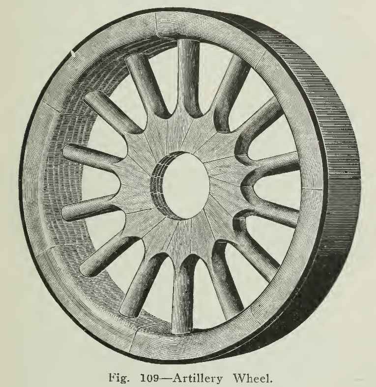
The wooden artillery wheel shown in Fig. 109 is practically universally used on all motor vehicles. The artillery wheel is very satisfactory inasmuch as the second growth hickory used in its construction combines the features of strength and resistance to shocks with light weight.
In the past few years the reduction in the supply of first-class wood has made the introduction of the wire wheel more rapid, especially in Europe where the scarcity is more pronounced than in this country. Wire wheels (Fig. 110) are lighter than wooden wheels and the claim is made that they permit greater tire life by rapidly radiating the heat generated by tire friction. Inasmuch as the rim of a wire wheel is lighter than the felloe and rim of the artillery wheel there is less flywheel effect and starting and stopping may be accomplished with less time and energy. An essential difference between wire and wood wheels is in the manner in which the load is carried. In the wooden wheel the weight is carried by the spokes in the lower half of the wheel, while in the wire wheel the hub and housing is suspended from the upper half of the rim by the spokes in tension. For this reason it is said that shocks are absorbed more readily and that greater life may be secured horn tires.
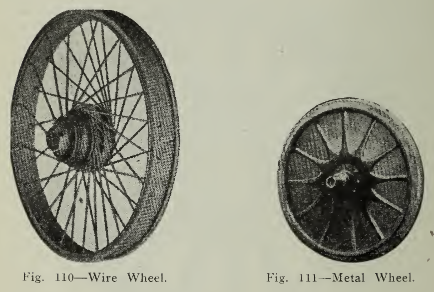
Fig. Ill — Metal Wheel.

Metal wheels (Fig. 111) formed by the use of two steel discs, suitably held by the hub and rim, are being used in trucking service for special purposes, such as enclosing motors or gearing in the wheel proper. The manufacturers claim strength and resistance to side-thrusts combined with lightness as their features and practice appears to verify the statements.
Rims. The rim is essentially a steel band designed to rigidly hold the tire and permit of its ready application or removal. The rim either encircles the wheel felloe or is secured to a band which does. If the felloe band and rim are separate then it is said to be a demountable rim (Fig. 112. A locking device, of screws, bolts or clamps, designed to hold the rim rigidly in position yet easy of removal, is a necessary part of a demountable rim.
(For description See page 238)
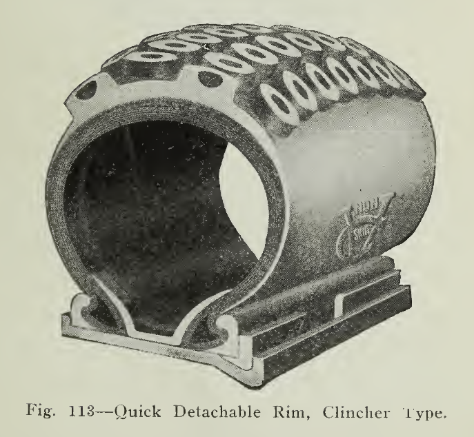
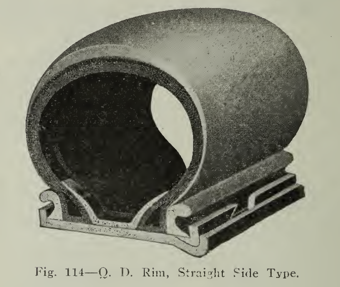
The shape of the rim section as shown in (Fig. 113) determines the type of tire to be used. For pneumatic tires the rims are known as (A) clincher or (B) straight side. These names are descriptive of the method employed in securing the tire to the rim. The hooks of the clincher rim engage with the hooked beads of the clincher tire so that when, inflated there is small possibility of the tire coming off. In fact, the trouble, is, that when the tire has been on for a length of time and is firmly seated by rusting or otherwise, there is difficulty in removing it for repair or renewal. To obviate this difficulty, which is most marked with the larger sizes of tires, the outside hook flange is made as a removable ring held in place by a locking ring. This construction is known as a quick detachable rim. Instead of the clincher tire, a straight side tire is often used so that instead of the hooks of the removable ring being curved inward as with the clincher tire, they are reversed, curving outward.
Many of the dimensions of the wheels and rims most commonly used have been standardized by the Society of Automobile Engineers, so that tires of any make whatsoever may be used interchangeably on a standard dimension wheel.
Rubber tires may be readily classified as pneumatic, cushion and solid. As the use of wood and steel tires are not recommended for electric vehicle service, except trailers, the following paragraphs will be confined to the construction and care of rubber tires.
The pneumatic tire is a combination of rubber compound and cotton fabric, so proportioned and interwoven that the complete unit may not only confine the air for cushioning but also withstand the wear and tear of hard use. Resiliency makes demands which cannot wholly be satisfied if endurance is kept in mind so that, a compromise must be effected giving the required cushioning with the least sacrifice of durability.
The modern efficient electric vehicle has been developed from the earliest type, net by radical changes, but by the refinement of the parts; by the reduction of waste power to a minimum. At first, tires were used which had satisfactory wearing qualities, but being hard, made it necessary to lift the weight of the car over every obstruction and out of every small crevice. As this took energy, means were found to design a tire which absorbed these inequalities of road surface of its own accord. The battery, therefore, having a definite capacity, could utilize it to propelling the vehicle forward instead of lifting it over thousands of small obstructions. This improvement is specifically due to the use of more elastic compound and a different weave of fabric. At first strength was sacrificed for this efficiency but today after years of experiments and steady service, tires are giving not only efficient mileage per charge of battery but also long life.

This point is important, and although lower first cost may seem to justify the use of less efficient tires, a moment’s thought should be sufficient to emphasize the additive loss during months, resulting from their use. In the case of the gasoline motor vehicle this refinement in tires is not so necessary since the continued supply of energy depends upon the size of the gasoline tank. With the electric; however, the charge in the battery is fixed and it is not a matter of how much more gasoline, but what reduction in mileage. The question of tire efficiency applies to cushion and solid rubber tires as well as to pneumatic tires.
The essential parts of the pneumatic tire are shown in (Fig. 117) illustrating the regular clincher type. The parts are known as tread, breaker strip, side walls, cushion, fabric and bead and meet the following uses.
The tread is the portion of rubber compound which is in direct contact with the road surface and of all parts is most subject to wear. It must resist wear due to the weight of the vehicle and in the case of rear tires, due also to the strain of traction. On good smooth roads this is not excessive but becomes quite a feature in slippery places where the wheels may slip and spin, bringing gashes and cuts into the material. While it is advisable to have the tread thick from the standpoint of good wearing qualities, resiliency and weight are items which must be considered in the choice for most efficient results. Careful study and exhaustive experiments have lead the manufacturers to their conclusions in the production of a suitable tread.
The breaker strip immediately beneath the tread is used to receive and distribute the force of the shocks over a wider surface. It, as well as the other fabric parts of the tire, is made of specially treated cotton. The walls on the side of the tire are made of alternate layers of fabric and rubber so that sufficient strength will be given to resist the bursting stress of the air within and yet be sufficiently resilient to do the greater part of stretching in the operation of rolling. The cushion shown between the breaker strip and inner fabric is of very resilient rubber and is an additional factor in shock absorption. The fabric is usually made of what is known as combed Sea Island cotton "frictioned" or pressed between and impregnated with fine Para rubber. The fabric gives the strength to the tire, is protected and the layers combined into a unit by means of the rubber. During the building up process, when layer after layer is added, the parts are formed gradually into a finished unit by the "curing" or heating process and finally the completed tire is vulcanized into finished shape.


The bead is made of fabric saturated with rubber and pressed into the desired shape. It may contain material such as steel wires or hardened rubber in order that it may be firmly secured to the rim when inflated and yet be readily removed for repair or removal.
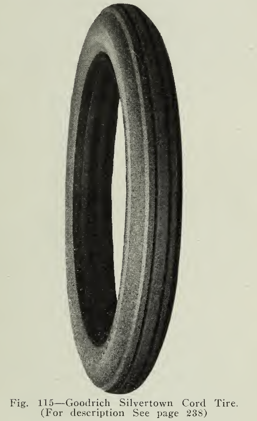
GOODRICH SILVERTOWN CORD TIRES.
A number of years ago a discovery was made in Silvertown, England, which has had a pronounced effect upon the successful operation of electric vehicles in this country. It was a new method of manufacturing pneumatic tires by supplanting fabric with heavy cabled cords made from sea-island cotton, and sole American rights to the manufacture of this type of tire were, secured shortly after by The B. F. Goodrich Company.
After a number of years of development which were necessary to fit the tire for use on American roads the new justly-famous Goodrich Silvertown Cord Tire, was placed upon the market.
While this tire has been' very largely used on gasoline cars, it may be regarded as a tire type particularly fitted for use on electrics.
Two rows of cabled cords, each thoroughly impregnated with rubber, driven in under terrific pressure form the carcass or foundation of the tire.
The advantages which the cord construction has over the fabric tire are far greater than would be supposed by anyone who had not given the matter consideration. The cords seem to have greater vitality and strength, and at the same time to be more pliable and resilient so that the tire not only gives long mileage, hut increased the radius of car activity per battery charge as high as 25%.
The tires absorb unevenness of the road surface, it is not necessary for the battery to push the car up and over obstructions; it is possible to develop greater speed, start quicker, coast farther and steer easier.
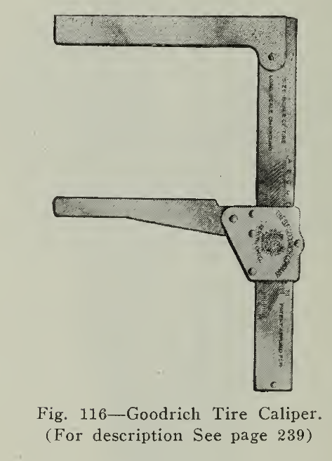
GOODRICH TIRE CALIPER.
Over-loading is acknowledged to be the most extensive and injurious of all the abuses to which pneumatic tires are subject. Some manufacturers have stated that as high as 90% of the tires which fail to reach their mileage expectancy, do so because sufficient air pressure has not been carried.
The proper inflation for a pneumatic tire has always been a source of disagreement. Obviously it is foolish to inflate a 4" tire which equips a light roadster and carries only 50O' pounds weight to the same pressure that a 4" tire on a heavy touring car and carrying 750 pounds weight is inflated. And yet manufacturers have heretofore advised an arbitrary inflation of 18 or 20 pounds pressure per cross sectional inch of the tire regardless of the weight which it carried.
Recently seventeen of the largest tire manufacturers have acknowledged that such recommendations were wrong; acknowledged that a tire should be inflated for the load which it actually carries.
The Goodrich Tire Caliper has been devised by The B. F. Goodrich Company to relieve this situation and to give users of pneumatic tires an easy method of determining proper inflation. By adjusting the caliper so that the two arms touch the sides of the tire a reading on the scale, entitled "Size Scale of Tire" may be secured. A corresponding scale entitled “Load Scale on Ground” provides for a 9% difference between the measurement at the top of the tire and the point where it rests upon the ground. By sliding the movable arm of the caliper to the corresponding figure on “Load Scale on Ground” and then fitting it over the tire at the bottom, motorists may determine whether or not there is too much flattening or deflection. Engineers state that deflection greater than nine per cent, is injurious to the tire carcass. If the deflection is greater than that figure the caliper arms will not fit over the tire at the bottom.
The use of the caliper is exceedingly simple; it is not necessary to remove dust caps or valve caps unless inflation is found to be necessary. The caliper is also as accurate as a steel tape in direct contrast to the spring gauge which often weakens, breaks, or is thrown out of adjustment by rust or particles of dirt.
If the caliper is not used it is necessary to weigh first the front end of the car, then the rear end, divide each weight by two in order to determine the weight upon each tire, and then determine from a table of recommended pressures the inflation which the tire should carry. With this figure secured the tire may be, inflated and gauged with a pressure gauge. Should that be inaccurate, the motorists will be unable to inflate the tires to the exact pressure which they should carry.
The tire caliper has been adjudged by men of authority as the only scientific, unfailing method of determining proper tire inflation.
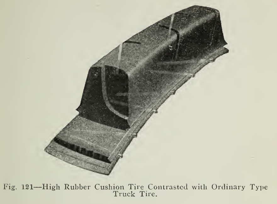
In cushion tires, the, object sought is to obtain freedom from punctures, blow-outs, etc., secured in the solid tire together with the resiliency obtained from the pneumatic tire. This is accomplished by proportioning the quantity of rubber in the compound and by the method of arranging the supporting ribs or bridges. The surfaces of the tread in some cases are grooved or cupped in order that firm traction and avoidance of skidding may be secured. These tires are held to the rim in a similar manner to the pneumatic tires and the latest designs allows for interchangeability with the latter. This form of tire is applicable both to passenger and light commercial cars, the conditions of load and speed being the governing specifications as may be readily understood.
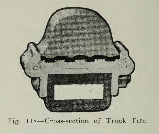
There are many styles of solid tire, some forms of which are shown in Fig. 118A. They differ in the method of attaching to the rim, either being secured by simply a clincher rim or fitted with transverse wires held under the hooks of the rim flange or containing longitudinal wires either at the center, near the rim or at the side. Another method of holding the rubber firmly to the base is by making the base of metal dovetailed to hold a hard rubber sub-base .and vulcanizing the tire to it. This practice is applicable for the largest tires and is shown in Fig. 120.
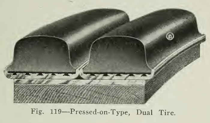
Tires may be arranged either single or dual, depending upon the weight to be carried, generally single in front and dual on the rear wheels, as 6 o% of the normal load may be considered as supported on the latter.
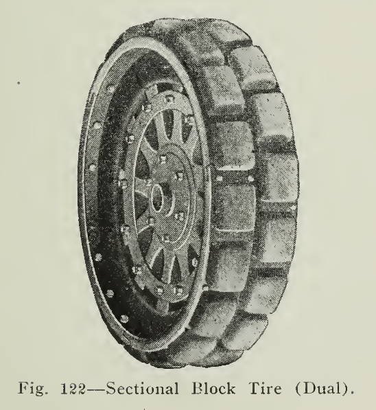
A type of solid tire which meets the requirements of heavy vehicle service is the "sectional block tire." (Fig. 122.) The advantages claimed for this style are greater life, greater resiliency and less cost of renewal, as the sections may be replaced individually, not necessitating the application of a complete tire when the damage extends to but a limited portion.
CARE OF TIRES.
Whether the tire be used in passenger or commercial service, the desire to secure continuous service with the least delay and expense is common. Although the pneumatic tire is most vulnerable, yet there are precautions which apply to all rubber tires because they are rubber, and therefore susceptible to the abuses which rubber will not withstand.
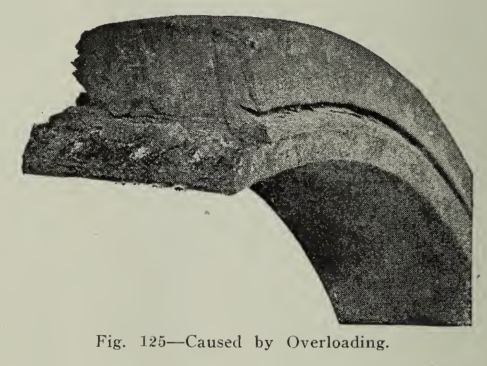
Elasticity is a characteristic of many substances, but the bare mention of the word brings to our minds the ability of rubber to suffer distortion and return to its original shape. Yet rubber, like steel, when strained beyond its elastic limit, will not return to shape. The fibres or small particles possess the ability to hold together and resist motion, but when their resistance has been exceeded they are permanently separated and their power of cohesion is lost. In other words, the material is said to be overloaded. Apply this explanation to a rubber band which we stretch, or a rubber tire which we compress, it is evident that the results are the same. A tire of a given size is designed and recommended after tests to carry a given load indefinitely. It is not reasonable to expect it to carry twice or three times the load continuously, yet unconsciously a large number of users continually overload their tires and are at a loss to understand their early failure.
When the tires are installed to carry full load distributed over the vehicle, it is evident that piling it upon the rear end for easy removal by a lazy driver exerts unnecessary strain on the tires. Considerable overhang produces a powerful crushing leverage amounting in effect to a heavy overload. When it is possible to unload a truck should not be allowed to stand over night fully loaded.
Over-speeding is responsible for many accidents and casualties and is to be heartily discouraged from every standpoint. In this connection it is well to consider the blows to which the tire is subjected when striking an obstacle at high speed. As a rule the maximum speed of the electric vehicle lies within the range dictated by safety and economy, so that difficulty from this source is reduced to a minimum.
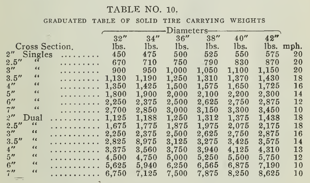
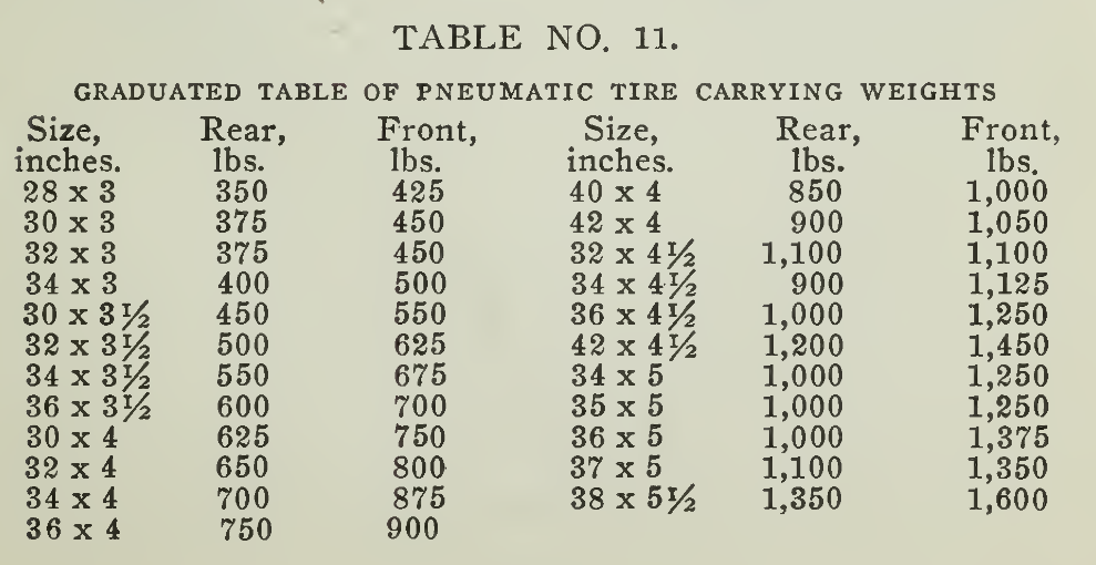
When passing over railroad tracks or ruts care should be exercised so that the blow may be as small as possible. Similarly, in backing against a curbstone, it should not be used as a stop placed there for the convenience of the driver. The deterioration produced by the several forms of abuse known as overloading may not be even visible to the eye, but the results will in time show up and the failure be unjustly laid to faulty material or poor workmanship. It has been estimated that 5^ excess weight added to the vehicle imposes an overload of 15% in wear and tear on tires. The salvation is in prevention alone. Tires which are too large, "oversize," are a profitable investment in the long run over a scant equipment. The following tables are appended representing safe load capacities:
ALIGNMENT
It frequently happens that a glancing blow against a curbstone or road shock causing bent axles or wrenched steering knuckles takes the wheels out of true. When thus out of alignment, the tire not alone rolls, but turns in another plane, SO that, besides requiring more energy for propulsion, the tread of the tire is ground off as surely as if it were held against a grindstone. (Fig 123.) Accidents of this nature should be remedied at the earliest opportunity by properly aligning the wheels. If the distance between the rims of the two front or rear wheels is the same at front and rear points, then the alignment is correct.

Fig. 124 — Running in Car Tracks.
OIL AND GREASE
Oils and grease in their proper place are very important factors in maintaining smooth operation, but when applied to rubber tires, the result is the ruin of the tire. The compound is attacked and reduced to the consistency of mush losing its resiliency and resistance. The garage floor should be kept free ‘of oil and the tires kept clear of puddles of oil if they are present. Gasoline may be used to remove oils or grease from the tires, as it dries very quickly.
ABRASION
There are very many ways in which the rubber may be worn off the tread or sides of the tire. Among these may be mentioned tires out of alignment, cuts from new roads of broken stone, car tracks and scraping against curbstones. Running with the tires out of alignment wears the tread very rapidly, as has been described.
Small cuts from litter or from sharp stones are not serious in themselves, but when neglected, dirt and sand work their way in, making the cut larger, and injuring a considerable portion of the tire. In the case of pneumatic tires, the sand works its way in between the rubber and the fabric, and with the help of moisture weakening the piles, a "blow-out” results. The small cut should be repaired at the earliest opportunity by vulcanizing as explained on (Page 252).
Running in street car tracks (Fig. 124) and against the curbing are very similar. The sharp edges of the rail flange cut small pieces off of the sides of the tire and in some cases, such as running over a frog which has been worn to a knife edge, leave big gashes which spell disaster. Granted that it is a big temptation to ride in the trolley tracks rather than bounce over cobbles or Belgian block pavements, yet it should not be indulged in except with the understanding that it is very damaging to the tire. In wet weather the effects are most pronounced, as rubber may be cut very much more readily when wet than dry. Small tires naturally sink deeper into the rail channel and thus have their sides worn away more rapidly than larger tires, which sustain the damage on the tread.
Starting and stopping give ample opportunity for excessive wear. There is probably no one with the least observing turn of mind who has not seen cars started from rest with a jump to run off at high speed. Such action causes a severe strain upon the tire and its fastenings, and really is a form of overloading the elasticity of the rubber. With heavy loads there is a great tendency to tear the rubber and fabric from its anchorage. Easy acceleration will do much to prevent injury from this cause.
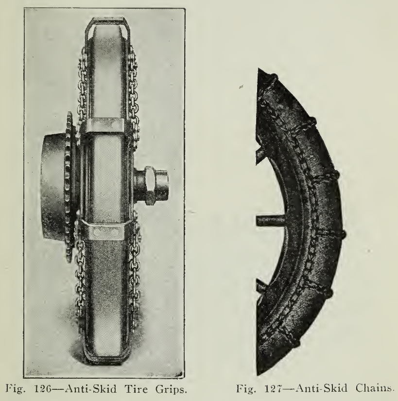
Fig. 127 — Anti-Skid Chains.
Likewise, who is there who has not seen a driver slam on his brakes and bring the car to a grinding stop? No motorist in his sane moments would think of holding his tire against a grindstone, yet those who suddenly apply the brakes and slide the locked wheels over the road surface, are guilty of exactly that offense. Yes, there are emergencies when danger of accident may even make reversing the driving mechanism necessary, but those instances are usually far and few between, and our arraignment of the thoughtless ones is just. The vehicle should be gradually brought to a standstill by slowly increasing the brake pressure.
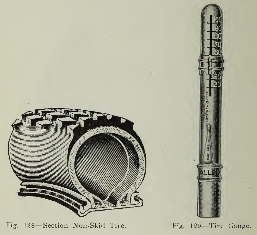
Fig. 129 — Tire Gauge.
While speaking of brakes, it is well to remember that the braking should not only be gradual, but that it should be equal upon each wheel and tire.
Adjustments are provided so that the pressure may be equal upon each wheel and periodic inspection should be given to this important item. When one wheel stops the car then the entire grinding action is borne by the tire of that wheel, being double the wear sustained when the slide takes place on both tires.
Skidding. Skidding, or the uncontrolled movement of the rear wheels on wet pavements in a lateral direction, is very often caused by unequal brake adjustment. Also, the momentum of the vehicle, tending to continue in its original path, after the front wheels have been turned, is accountable for this dangerous action. When possible, the front wheels should be turned in the direction in which the car is sliding, in order to counteract its effects.
Several means have been introduced, such as tire chains, grips and special treads (Figs. 126, 127) for the purpose of reducing skidding and securing better traction on wet or oily roads. Tire chains are effective and extensively used with satisfaction. They should be loose enough to slide around the tire so that the cross links may give traction to the entire tread instead of confining it to a limited number of points. For this reason it is better to have a considerable number of cross bars so that the blows as the tire grips the road may be increased in number, but decreased in magnitude. While indispensable for driving in congested traffic or slippery roads, they should be removed when the road conditions do not make them necessary. Under no condition should they be fastened permanently to a spot on the tire, as it would direct the entire driving strain to the small section thus confined, severely overloading its elasticity and resiliency. Finally, if the links have been worn sharp they should be replaced, as the sharp corners cut into the rubber of the tread.

Fig. 131 — Inner Tube Protector.
Fig. 132 — Folding Inner Tube for Storage.
At present there are many special anti-skid treads recommended by the different manufacturers, which have the one aim in view. The principle used is to effect the formation of a vacuum when there is a tendency to lateral movement. This is accomplished either by cups, small blocks or projections from the tread of many varieties of shape and kind. (Fig. 128.)
The question of routing has a decided effect on the wear of tires, so that whenever possible poor roads should be avoided or a detour made, as prevention is far better in most all cases than the cure. This is a very simple matter with passenger cars, but naturally might lead to complications with commercial vehicles. Having in mind the probable damage, however, means may usually be found to avoid stretches of sharp broken stone, deep ruts, etc.
Standing Idle. It is only natural to expect the rubber of the tire to acquire a permanent set or become flattened under several thousand pounds pressure. To avoid such strain vehicles should be jacked up and supported on horses (which may be very inexpensively constructed) when standing idle for any length of time. Heavily loaded vehicles should be relieved of their load when standing over night. With pneumatic tires not only is it necessary for the casings to withstand the pressure of the air within, but the weight of the vehicle, so that the importance of these simple means of relieving unnecessary strain should be evident to all.
CARE OF PNEUMATIC TIRES
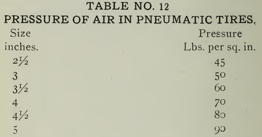
The most important thing to remember in the use of Pneumatic Tires is to keep them well supplied with air. It has been estimated that over three-quarters of the difficulties encountered by motorists are due primarily to lack of inflation. It is necessary to inflate the tire to the proper pressure specified by the tire manufacturer and given in able No. 12 below and keep it at that pressure as long as the tire is in use. There are remarkably few cases of over inflation except where air compressors are carelessly or ignorantly used. There is little doubt of the fact, however, that with a hand-pump, not over one man in a million has ever put too much air int6 his tire.
There is but one safe way to govern the inflation of tires and that is to purchase a reliable tire gauge and use it regularly for inspection and when inflating. It is impossible to tell by looking at the tire, kicking it or counting the number of strokes of the pump just what the pressure is. There is only one reliable means and that is the gauge (Fig. 129), which is inexpensive and certainly pays for itself many times over in tire savings.
An erroneous impression which seems to have received wide circulation is the idea that in hot weather tires should not be inflated to their standard pressure. Although the pressure in the tire is not wholly independent of temperature, yet the variation is so slight that it may be neglected for all ordinary conditions.
The pneumatic tire being constructed of rubber compound and cotton fabric, is intended to be possessed of strength to withstand the pressure from within, shocks from without, and offer resilience in motion. The side walls of the tire are subjected to a bending motion which is very pronounced and continuous when the tire is run soft or semi-deflated. This alternating bending produces heat just as the bending back and forth of a piece of wire makes the latter so hot that it cannot be comfortably held by the fingers. The heat thus generated in the threads of the fabric extends to the other parts of the tire and produces gradual deterioration. There are other forms of friction within the tire which generate heat which cannot be so easily avoided as the one just explained. The fabric within thus weakened may be readily broken by a severe shock or bruise and if not repaired will result in a "blowout."
Smaller cuts in the tread or side walls may be readily encountered and if not remedied at once gradually increase in size, causing more serious damage. Sand or dirt may easily work their way into the small cut, making it larger and finding a place between the rubber of the tread and the fabric make the gap larger and form a "sand blister" or "mud boil." These blisters continue to in- crease in size and speed, allowing water to find its way to the fabric. Cotton fabric is very strong when dry, but when exposed to dampness or moisture it rapidly loses its strength. It can be easily understood, therefore, that when a small cut is allowed to develop and water is permitted to attack the fabric, that a sharp shock to the material at the damaged point will cause it to give way and allow air to escape, in many cases ruining both the tube and the casing.
Another source of injury to the casing is the severe blow encountered at high speed. Although no evidence may be left on the outside of the casing and no trace of damage be found until a blow-out occurs, it may generally be assumed that the innermost ply of the fabric is broken. Gradually the plies above it having to endure greater strain, give way until the entire thickness of fabric is destroyed, and finally a blow at the damaged point causes a blow-out.
Under normal conditions of service the tread is gradually worn off and unless damaged by cuts will not need repairing until it is worn almost to the fabric. Obviously it should be retreaded before such a point is reached in order that the fabric may not be damaged either by being ground off or subjected to moisture.
Small cuts, as noted above, should receive immediate treatment by being cleansed of sand and dirt with gasoline or benzine. The sides and the space about one-half to three-quarters of an inch around the sides should be roughened by rubbing with sandpaper, the cut filled with patching cement, an application of rubber gum should then be worked into the cut and allowed to set for several hours before using the tire. This treatment will suffice for small cuts, but with larger ones vulcanizing should be resorted to.

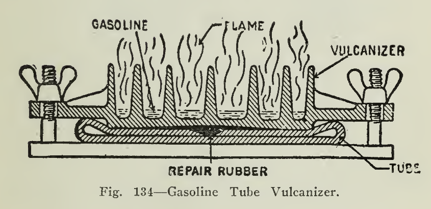
In the treatment of sand blisters or mud boils, they should be opened and the rubber cut away so that all dirt and foreign material may be removed from between the rubber and the fabric. After cleansing thoroughly with gasoline, the good tire surface around the edge of the cut should be roughened and several applications of cement given. The cement should be allowed to dry thoroughly before each application and the rubber gum added and vulcanized into place. Vulcanizing may be done either by the acid cure vulcanizer or by one of the mechanical types of vulcanizers such as those heated by gasoline, steam or electricity (Figs. 133-136).
Vulcanizing. Uncured rubber stock is used as a filler in replacing the material which has been cut out of the tire or removed by a blow-out. The vulcanizing cement is different from that used in making ordinary repairs, in that it contains a small amount of sulphur which cures the Para stock integrally with the old material. It is necessary to regulate the heat carefully, as the vulcanizing may be effected best at a temperature ranging from 250° to 275° F. Material which has been previously treated should be worked at a lower temperature than new stock. As explained above, the cut or punctured tube should be thoroughly cleansed and roughened with sand paper, after which two coats of the vulcanizing cement may be applied, allowing the first to dry before the application of the second. Strips of rubber are then cut to fit into the opening and a piece of cloth applied between the face of the vulcanizer and the rubber This treatment of from fifteen to twenty minutes at the proper temperature will effect the repair of any ordinary damage. Should the cut be very deep it may be necessary to fit in several layers of rubber, all of which may be vulcanized in one treatment.
Acid Cure. In applying a patch with the acid cure outfit it is also important to clean the surface thoroughly and when the acid has been worked over the cement, the patch should be rapidly placed in position and smoothed down forcing out all air bubbles and if possible clamped tightly to dry. In making repairs by patching, the proper time to apply the patch, which also must be prepared with cement, is when the second coat has become "tacky," that is almost dry but sticky. It is well lo have a clamp for this so as to insure better contact of the patch over the damaged part.
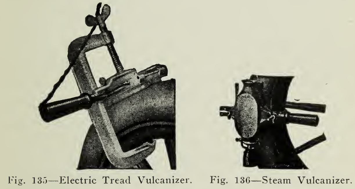
Fig. 136 — Steam Vulcanizer.
A number of vulcanizers of the several types mentioned are shown in the accompanying illustrations, the principle being the same in each, the difference in the means by which the heat is furnished and regulated.
For the temporary repair of a blow-out, the most convenient method is to apply the inner tube protector (Fig. 131), to prevent the inner tube being cut by the jagged edges of the casing. A bandage (Fig. 130), may then be laced or securely fastened over the damaged portion of the casing to prevent dirt or pebbles from entering. This is a very satisfactory means for repairing the blow-out sufficiently to reach a repair station.
The damages which extend through the body of the tire tearing the fabric as well as the outer coverings, necessarily require more extensive handling than has been detailed above. When the plies of fabric are broken it is necessary to cut away the successive layers in slightly increasing size over the opening so that when new material is added with sheet rubber between to effect a solid joint, the joints of each layer will overlap.
Attention should be given to the rims as in many instances the hooks of the flanges become jagged or sharp and wear into the fabric near the bead so that a good jar may produce a blow-out. Rust is also a foe to be contended with as it is destructive to the rubber and fabric. For this reason the rims should be kept free of water and moisture and if the rims become rusted they should be cleaned off with emery cloth and given a coat of aluminum paint or shellac. This treatment should be afforded at least once a season as it not only prevents rust but makes removal of the tire easier in case of puncture.
Inner Tubes. The inner tubes should have a life greater than the casing and this is usually the case if properly cared for. The inner tubes should be protected from light, grease, oils and sharp tools. It is not infrequent that we see inner tubes carelessly folded, thrown in the tool box to bounce and knock around with sharp edged tools and oily waste. Tubes handled in such a manner are hardly fit for use when installed as the oil has attached the fine rubber and the tools have probably produced cuts.
The inner tube should be carried in a special bag or wrapped in soft rubber wrapping, being sprinkled with soap stone or French Chalk. The illustration (Fig. 132) shows the method of folding the tube so as to expel all the air without excessive creasing. After removing the valve stem to allow the escape of air, the tire should be handled as shown in (a), (b) and (c). Compressing the tube as in (c) the stem and cap should be replaced when it may be folded as in (e), (d), (f). The bands used in tying should not be tight and the tube should be refolded at intervals so that the folds may not develop sharp creases which weaken the structure.
It sometimes happens that a small nail punctures the tire and gradually works its way around making punctures at several points by circumferential movement of the casing on the rims. Before inserting a new tube, it is always well to run the hand around the inside of the shoe to make sure that there is no obstruction to cause damage. The use of soapstone or French Chalk is recommended to prevent the generation of heat between the tube and fabric of the casing. Powdered graphite is also efficient as an anti-friction material.