Last Update: March 10, 2018

There are two broad divisions in the field of electric cars, commonly designated as passenger and commercial vehicles. The former include the small runabouts, coupes or limousines, while the latter are commonly called trucks. In this latter classification should also be found the industrial vehicles electrically propelled, such as baggage and dock trucks as well as storage battery cranes and locomotives. To develop detailed descriptions of the many forms in which these vehicles may be found is neither practicable in a volume of this character, nor is it necessary, as the principles are identical in all storage battery vehicles, and, when once understood, the differences in design may be readily grasped.
The construction of bodies has received skillful and exact treatment for many years. Coach-building is not a new industry by any means and the advent of the automobile has simply opened a broader field of endeavor to the artisans of that trade. True, the shapes and materials used have changed somewhat, but in the pleasure car, the requirements of comfort and protection from wind or weather are identical The lines of the body are shaped so as to be pleasing to the eye and oppose the least resistance to the wind. The necessity for strength and light weight have brought about the use of aluminum for panels, moldings and seams, displacing wood to a great extent.
The utmost simplicity and economy may be observed in the design of bodies intended for salesmen's, inspectors', or other business runabouts, while on the other hand the identical chassis may be surmounted with an enclosed type of body, which, in lavish furnishing and refinements for luxurious comfort, might excel the splendor of royal equipages. The features of strength, simplicity and economy of operation, however, are as well developed in the most commonplace looking carrier of merchandise, as in the most exquisitely furnished brougham. The trimmings and fittings are matters of taste and choice, dictated by the requirements of the owner.
With the introduction of the motor vehicle into the transportation departments of the various industries, new requirements were placed upon the design of the chassis and bodies used. These were the result of carrying heavier loads and moving at higher speeds than were possible with the horse drawn vehicles. As one of the economies of the motor vehicle consists in moving its loads at these greater speeds, innovations were made in providing many varieties of .special bodies, combining strength, light weight and quick loading and unloading facilities. Bodies of such construction are characteristic of motor vehicles in general and no doubt familiar to all.
In electric vehicle practice the word chassis !s used to designate the parts of the car other than the battery and body. These parts consist of the wheels, frame and supporting springs as well as the controller, motor, gearing and steering apparatus. The motor and controller are pieces of electrical apparatus and are treated separately in Chapters IX. and X.
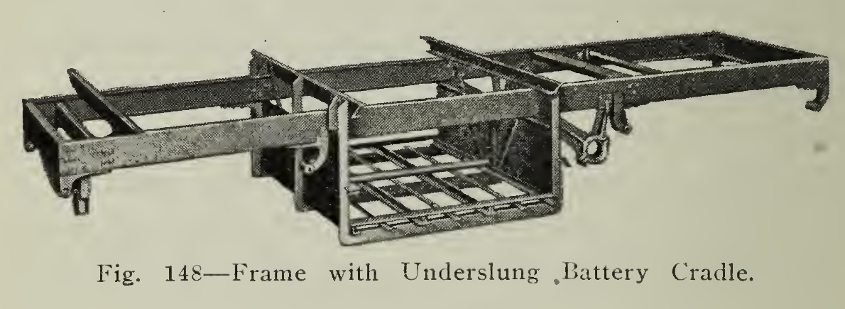
Frame. The body with its load is supported upon a strong, but somewhat flexible, structure known as the Frame (Fig. 148), which in turn rests on springs attached to the front and rear axles. By this arrangement, as much of the weight of the vehicle as possible is carried on the springs, cushioning the shocks and reducing the vibration.
The frame is composed of two side members and several cross members, so that with proper riveting the parts may be combined into a unit of sufficient strength to carry the load and maintain the proper relation between the sections of the driving gear under the road shocks or the distorting effects of the inequalities of the road surface. Bracing straps, gusset plates and kindred means of reinforcement are used to effect the desired result. Pressed steel forms are usually made use of for the purpose as they combine the requisite strength with light weight. The frame shapes differ widely, depending upon the size and service requirements of the vehicle. Very often the front ends are cambered to permit turning in a smaller radius. The outsiders and spring stubs are forged steel and are riveted to the ends of the side members.
In pleasure vehicle construction the frame is frequently raised at a point in front of the rear axle to permit the running board and floor of the car to rest lower than if the entire frame were on one level. It is necessary for the rear part of the frame to be high enough to provide sufficient clearance between the cross members and the rear axle housing.
The storage battery assembled in several trays may either be underslung from the frame in a cradle or carried on cross members. While there is no rule or standard practice in this regard, it will usually be found that, with commercial vehicles, the battery is underslung, and that in pleasure car design the number of trays are divided and supported slightly below the frame level under hoods at the front and rear. Electric vehicles may be readily recognized at a distance by these characteristic features of arrangement.
Springs. In order that the shocks and jars incidental to travel over roads not absolutely smooth may be absorbed and not transmitted to machinery and passengers, considerable attention has been given to the construction of springs. Special formulae have been developed for treating the steels used, and extreme care is exercised in the fabrication of the leaves so that the built leaf spring will be able to absorb the shocks and vibration, and, at the same time, carry a considerable weight without sustaining permanent deflection or breakage. The length and form of spring used, such as elliptic, semi-elliptic, three-quarter elliptic, helical or platform, or combinations of these, depend upon the weight, speed and class of service in which the vehicle is to be used as well as upon the individual choice of the designer.
The springs rest upon specially formed seats forged from the axle proper or welded to it. These seats are curved so as to conform to the curvature of the spring and are drilled so that two "U" shaped rods of steel, known as clips, may be brought over the plate resting on the upper spring leaf, through the holes of the seat, and secured by nuts and lock nuts. The ends of the springs are connected by bolts and bushings. As there is great opportunity for wear at these points, grease or oil cups are usually furnished for lubricating these bearing surfaces.
Axles. Axles are very important parts of a motor car chassis because, upon their freedom from failure, depends the safety of the passengers. To fulfill this requirement, as well as to support the load properly, they must be strong.
Front axles not only support their share of the load, but are first to receive the shocks and jars due to holes and ruts in the road. Strength is required to meet these demands, and then comes the consideration of utilizing the least weight of material sufficient to provide that support. Steels of special composition, properly forged and heat treated, have been developed in order to combine the necessary strength with light weight. Front axles of I-beam section are probably most extensively used, although tubular shapes have been popular on the lighter types of electrics.
Reference to Fig. 149 will clearly indicate the assembly of the axle ends by means of which the steering mechanism is combined with the load supporting members. The ends of the axle are yoked so that a knuckle with spindle for the wheel and steering arm may each be mounted in anti-friction bearings, thus permitting both free rolling of the wheels and steering with a powerful leverage. The projecting arms of the knuckles at each end of the axle are connected by a "cross rod" or "tie bar" so that the movement of both wheels in steering will be identical. The motion imparted by the steering gear is transmitted to the tie bar by a rod known as a "drag link." The connection between the drag link and steering arm is either a ball and socket joint, enclosed in a grease boot, or a yoke and pin arrangement provided with bearings.
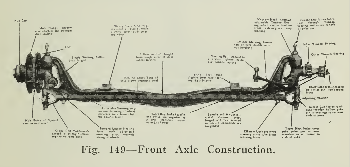
It will be noted that all bearing joints, susceptible either to radial load or end thrust, are provided with anti-friction bearings so that wear and resistance to motion may be reduced to a negligible quantity.
The seats upon which the springs rest, and to which they are secured by the clips, may either be integral with the axle or forged separately and fastened rigidly to it. The upper spring seat surface is curved so as to give greater bearing surface for the spring, and, in some cases, tilted slightly to obtain a caster steering effect.

Rear axles may be divided into two classes, according to the service in which they are used; pleasure or commercial. Front axles are practically the same for both classes of service, the proportions being more generous, of course, when used upon trucks. Vehicles of light weight may use the construction developed for the pleasure car chassis, but those designed for heavy duty must necessarily be provided with rear axle equipment capable of transmitting power efficiently under the stresses of heavy load and poor road conditions. The live axle is characteristic of the light car, while the dead axle with countershaft and side chain drive is, with few exceptions, used on the majority of commercial vehicle applications. The live axle (Fig. 150) not only supports the load, but transmits the power from the motor, dividing it through the differential gear to the wheels. When the load is carried by the housing and the enclosed shafts transmit the power to the wheels, then the term “full-floating” is applied to the axle because the shafts are said to float within the housing. Semi-or three-quarter floating refers to axles in which the carrying and torque functions are combined in approximately the amount indicated in the term.
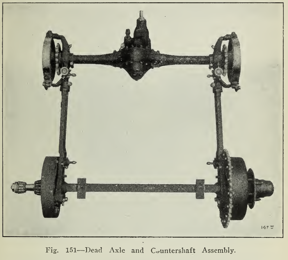
The dead axle (Fig. 151) is the familiar form which is used to support the load alone, the driving being done by chain gearing from the countershaft to the rear wheels.
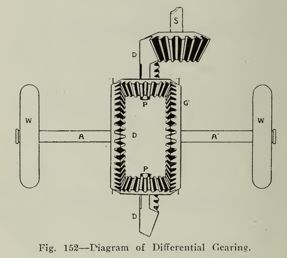
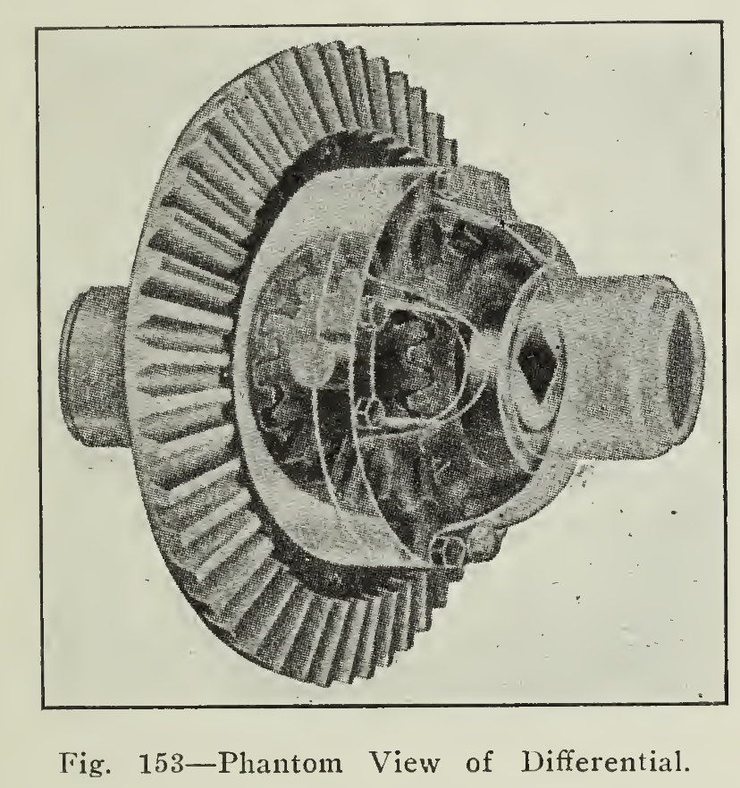
Differential Gear. In order that the power from the motor may be applied equally to both driving wheels and yet permit them to revolve at different speeds, as when turning a curve, the differential gear is employed. It is necessary with either live or dead axle construction. With live axles it is contained in the housing but with dead axle construction it is incorporated in the counter-shaft assembly. To reduce wear and make for efficient running the differential casing is made oil tight so that light grease or heavy oil may be held, making adjustment seldom required but assuring proper lubrication.
With the aid of Fig. 152, the following explanation may serve to give a clear idea of the operation of the differential, an important but unfamiliar detail of the transmission. In the illustration shown the driven gear D is meshed with a bevel pinion S on the driving shaft, but, of course, the driven gear may be of the spur type operated by silent chain or a gear meshed with a worm shaft. The four small bevel pinions P are held on spindles in the plane of the gear D, and their teeth mesh with the bevel gears G and G1 attached to the axle shaft ends. Thus, when G is stationary, the pinions P will roll over its surface and also upon their own axes, turning G1, if the resistance to motion of the wheel W is greater than that of W1, as in turning a corner, then G will turn but at a lesser speed than G1 When the resistance of both wheels is equal, then the gears G and G1 will be revolved at the same speed by the small pinions P which will not revolve on their spindles.
It will be seen that the shafts are mounted in bearings of design capable of taking the stresses of radial load or thrust so that the action will be smooth and quiet running.
Steering Gear. One of the most important mechanisms of any self-propelled vehicle is that used for steering. It must be simple and quick to operate and positive in action so that the direction of motion of the vehicle may be rapidly altered by the driver with little physical effort. The steering is effected by means of a series of links which transfer the small movements of the guiding wheel to the steering arms attached to the knuckles upon which the wheels are mounted, as explained above under "Axles."
The steering column is furnished at the lower end with some form of reduction gear when a steering wheel is used, which permits a small rotary movement of the steering wheel to be transformed to a reciprocating movement of the drag link. This gear reduction may be by pinion and spur sector (Fig. 154), spur gear and rack, or worm and gear. At the present time the pinion and sector type is very widely used on electric commercial vehicles.

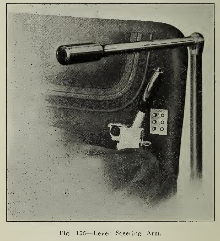
For light commercial and pleasure vehicles, the horizontal steering lever (Fig. 155) is very extensively used, being practically the standard on account of its big leverage and quick action. The horizontal lever is arranged to swing into a vertical position over the steering column to which it is attached out of the way of the driver when not in use. At the lower end a knuckle with a ball end rests in the socket of the drag link. These connections are usually furnished with ball bearing and spring adjustments so that friction may be reduced and the handle kept free of vibration Wheel steering gears are used on heavy vehicles, or on those which are to maintain much speed, be cause they are irreversible; that is, a jar or blow on the road wheels will not alter the direction of motion of the vehicle, as might occur with the steering rod previously described.
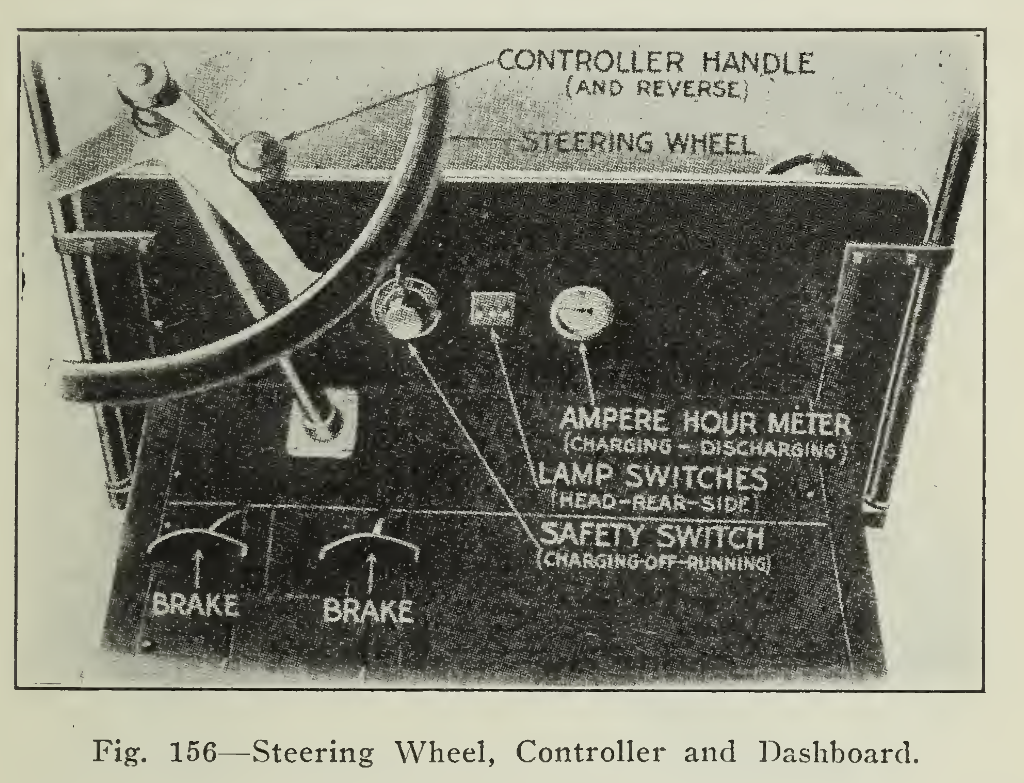
On the heavier commercial vehicles the steering wheel is standard and with it is very often combined the lever to the drum of the controller. Fig. 156 shows one method of arranging the controller handle upon the steering column in a manner similar to that employed in gasoline vehicle steering and control.
Bearings. It has been pointed out in the descriptions in the preceding pages how important a part in the operation of the electric vehicle anti-friction bearings play. In order that the greatest mileage may be secured from the battery capacity available, friction must be reduced to a minimum. Practically every moving part, which is susceptible to wear, is fitted with a type of bearing most suitable to the use. The designs. Fig. 146, show the several types very clearly.
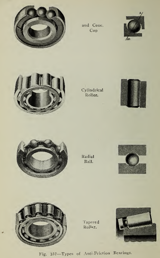
It will be found that, under identical conditions in cars of different make, different types of bearings are used. These differences of opinion naturally exist so that several styles of mounting are employed. With very few exceptions, inspection will show the bearing equipment to be of liberal proportions for the loads sustained in order that each running part may have the greatest freedom in motion.
Brakes. One of the most important features of the motor car control is the means used for retardation. If the car refuses to start, it is possible to get out and walk, but it is not pleasant to contemplate a ride down grades with brakes which are of little value. Vehicles of up-to-date construction are in practically all cases furnished with brakes of ample size to bring the vehicle to stop without jar or suddenness.
The brakes are operated by pressure exerted on the brake pedals situated within easy reach of the driver’s feet. The rods from the pedals usually transfer the pedal pressure to equalizing bars suspended from the frame so that the pressure will be equal upon both brake drums of the rear wheels or countershaft. Brake drums are placed in many cases on the countershaft for emergency brake use, and on the rear wheels for general service braking. Frequently hand levers with ratchet locks are used for emergency brake control instead of a foot pedal.
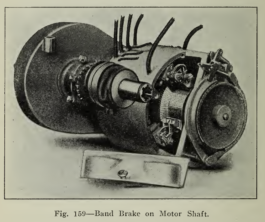
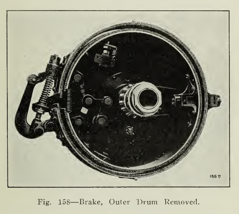
Most generally the construction of the brakes is of the type shown in Fig. 158. The two semi-circular shoes are pivoted at one end and held at the other by a cam or toggle linkage. The force exerted on the brake levers causes these links to expand the shoes against the surface of the drum, retarding the motion of the vehicle evenly and gradually. When the shoes operate on the inner surface of the drum they are called "internal expanding" and when the pressure is exerted on the outer drum surface, the term "external expanding" is used. A band brake is shown in Fig. 159, contracting on a pulley keyed to an extension of the motor shaft.
In this particular design, the friction brake is operated in conjunction with an electric brake. The electric brake is secured by short circuiting the motor armature through resistance, energizing the fields from the battery. The connections for accomplishing this are made when the controller handle at the left of the driver is brought back slightly beyond "off" position. Under these conditions the motor acts as a dynamo, using the momentum of the car to generate electricity. The greater the speed, the greater will be the braking action automatically. As the controller handle is brought back still further, pressure is applied to the band brake on the motor pulley exerting a very powerful retarding force. This combination is very powerful and quick acting because of the big leverage obtained through the reduction gearing. Some manufacturers of pleasure vehicles consider it very valuable in rendering braking and stopping physically easy and reliable for drivers of the gentler sex.
The brake shoes are faced with friction material such as the heat resisting substances composed of asbestos interwoven with copper gauze. These facings gradually wear down and must be renewed; how often renewal is necessary depends upon the amount of use to which the brakes are subjected.
Transmission. Experience has shown that electric motors of comparatively high speed, having ranges of from 900 to 1,600 revolutions per minute, are satisfactory for vehicle use. As the driving wheels travel at speeds considerably less that these, however, it is necessary to interpose some means of reduction gearing between the motor and the wheel. There are many methods of accomplishing this result such as by sprockets and chains, shaft and bevel gear, or worm and gear. Each of these means is both efficient and enduring, and represents the study and experiments of the most skillful designers, supplemented by many years of experience from the many vehicles in constant service.
Probably the greatest number of electric cars at the present time are equipped with a double reduction transmission. The first reduction is in many cases a silent chain gearing, enclosed in an oil tight case, so that the adjustments may be undisturbed by entrance of grit or rust. The larger sprocket of this reduction is connected through a differential gear on the countershaft to the rear wheels by roller chain drive, or by means of shaft with universal joints to a differential gear in the rear axle construction. In commercial vehicles the final drive from countershaft by side chains is most common, while the shaft drive is much favored for pleasure vehicles because of its neat, noiseless and efficient character.
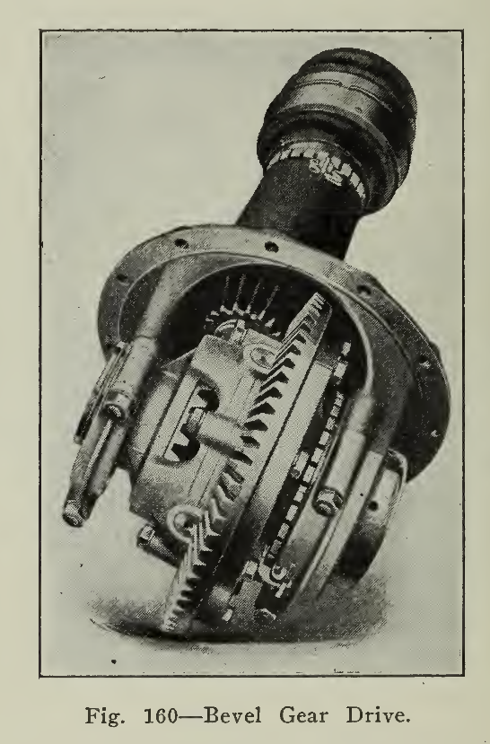
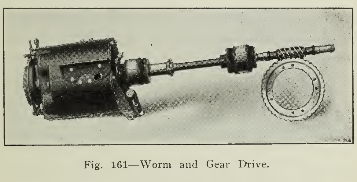
Shaft drives are used either with bevel gear, Fig. 160, or worm drive to the rear axle. The worm and gear reduction is the most recent of refinements in electric vehicle design. The illustrations. Fig. 161, show the features very clearly. The advantages claimed for the worm drive are that a greater ratio of speed reduction than practicable with bevel gears is possible, permitting a single reduction between motor and rear axle, and that instead of a tendency to wear out of alignment in course of time, as occurs with bevel gears, use makes the adjustment more perfect, providing that the design and initial adjustments have been correct. It is for this latter reason that the shafts for bevel gear drive are provided with means for making the necessary changes in adjustment, while the worm and gear mounting is enclosed so that changes cannot be made from without.
The ends of the shaft connecting the motor and rear axle constructions do not remain the same horizontal plane as the spring action raises and lowers the motor end of the shaft, under the influence of uneven road surface. In order to transmit the power to the rear axle efficiently, therefore, the shaft must possess flexibility to compensate for the changes of alignment throughout the range of spring action. This flexibility is secured by the use of universal joints of neat design, as shown in Fig. 162.
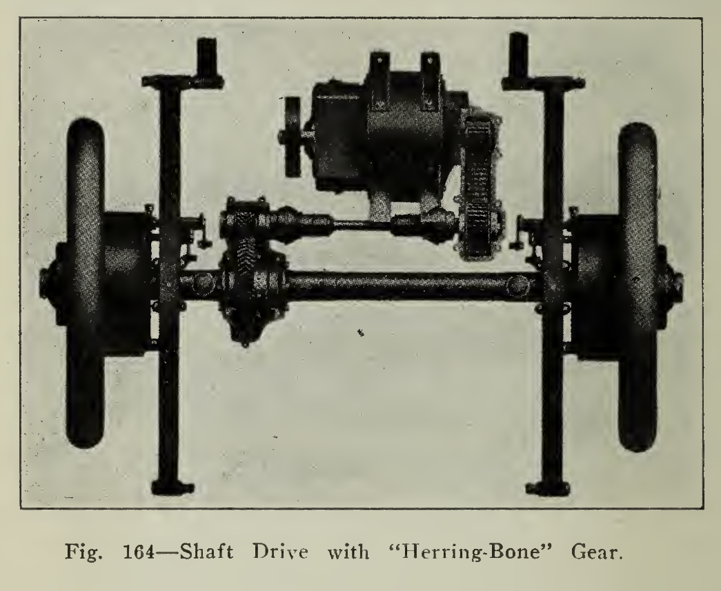
A unique form of drive is shown in Fig. 164, in which the motor drives through an enclosed silent chain and floating shaft, with two universal joints, to a “herring-bone’' gear connecting with the differential gear in the rear axle housing. The rear axle construction is arranged so that the axle shafts carry no load and the differential is relieved of end thrust. The outer ends of the axle shafts are furnished with clutches, engaging with the wheel hub. This type of axle is known as “full floating” because the load is carried by the housing and the axle shafts may be drawn out from the hubs without disturbing the rest of the assembly.

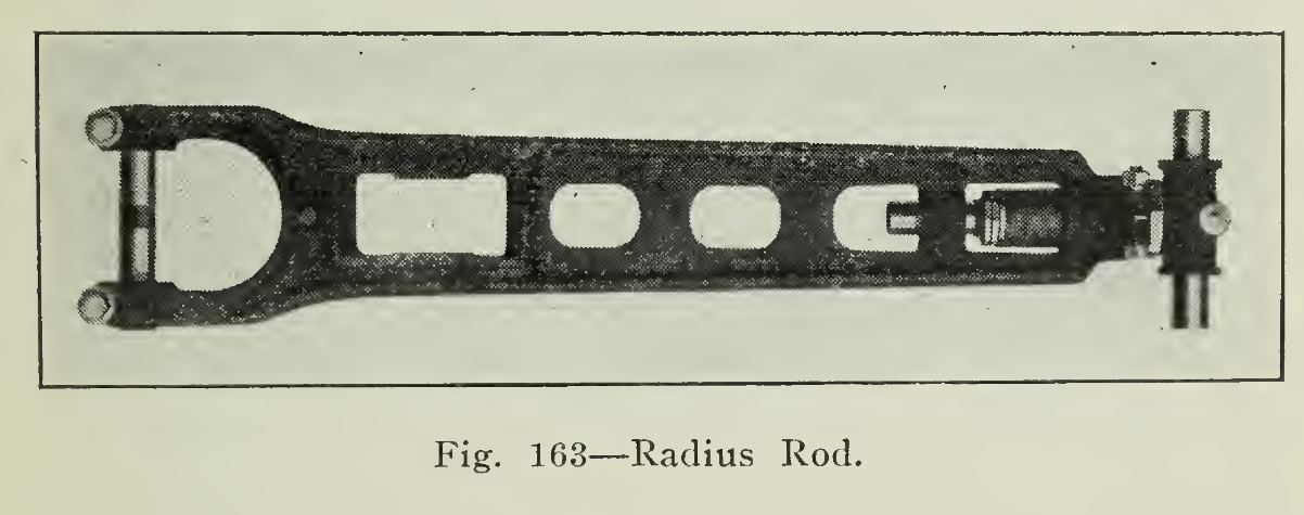
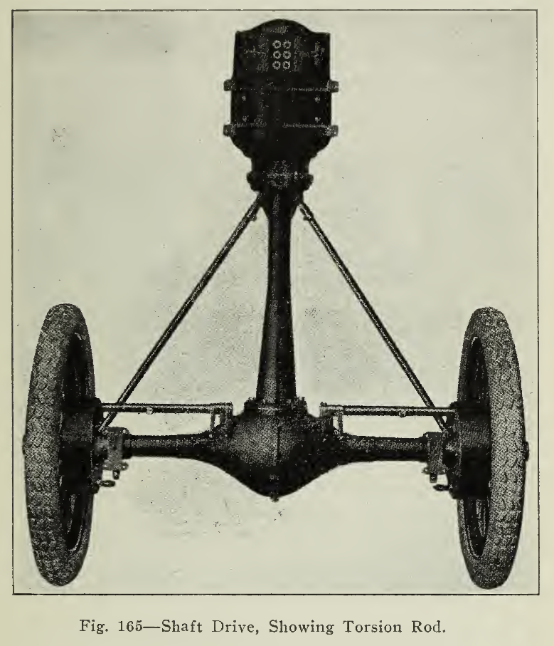
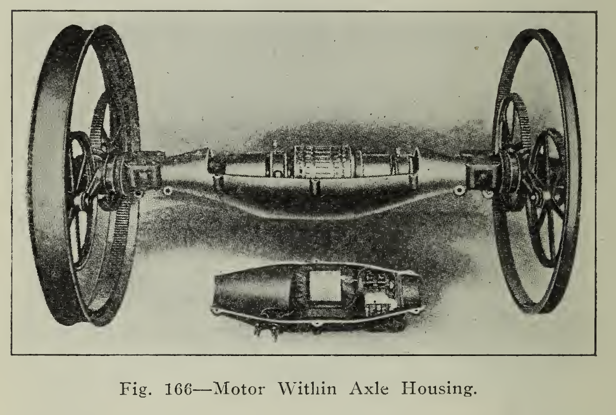
In order to preserve the proper distance between the sprockets of the chain gearing, adjustable spacing members are employed, called “radius rods” (Fig. 163). These maintain the chain in proper tension and secure the countershaft into a unit with the rear assembly. They are also used when shaft drive is employed to keep the rear axle in proper relation with the frame. In some designs the driving shaft is held in a tubular member, generally attached to the frame so that it serves as a radius rod, permitting the axle to move up and down, due to the influence of inequalities of road surface but not allowing end movement of the axle. When the torsional, or turning strains to which the axle housing is subjected when driving, are taken by a single member, it is known as a "torsion rod" (Fig. 165) Instead of supporting the motor from the frame, the design of drive shown in Fig. 166 makes use of a motor enclosed in the rear axle housing. The shaft of the motor armature is hollow so that the drive shafts may extend through from the differential sockets into the centre of each hollow rear wheel. The differential is located at one end of the hollow armature shaft. On the wheel end of each shaft a pinion is located which transmits the power to the rim gear on the inside of the wheel through the two idler gears. The fully enclosed construction and simplicity of the parts are claimed by the manufacturers to be important factors in making the drive efficient and durable.
In the descriptions of drive methods typified in the preceding paragraphs, reference has been made only to the use of one-motor equipments. Although the earlier electric vehicles made use of two motors geared to the wheels by single spur gear and concentric rack, avoiding the use of a differential gear, this design is restricted at the present time to special cases. Such instances are those where considerable traction is required for moving heavy loads over difficult road conditions. Then two or even four motors may be utilized, securing additional traction by the use of the front as well as the rear wheels for driving.
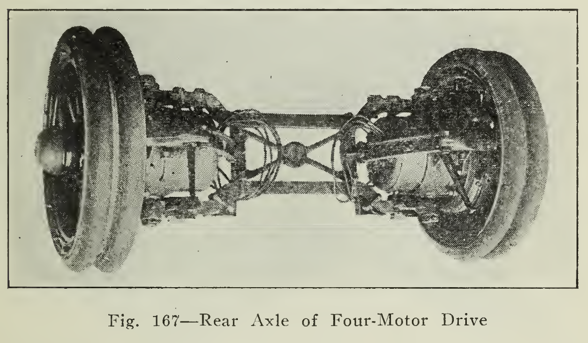
In Fig. 167 is shown a rear axle construction used on a seven-ton, four-motor truck. The axle forgings are made of yoke form in a vertical plane and bored out to receive the trunnions which are part of the motor casing. The motors slip into these casings and are clamped in position. A pinion on the end of the motor shaft engages with a spur gear meshing with an internal gear bolted to the wheel. This gearing is enclosed by projecting flanges ground to form a grease tight joint. At the front the two casings swivel in the axle and are connected to the steering gear. At the rear they are maintained in fixed relation, holding the wheels permanently parallel and in line with the truck.
A two-motor drive is shown in Fig. i68. The spur concentric gearing is enclosed in this design also, and the motors are held in position between two steel channels which form the rear axle.
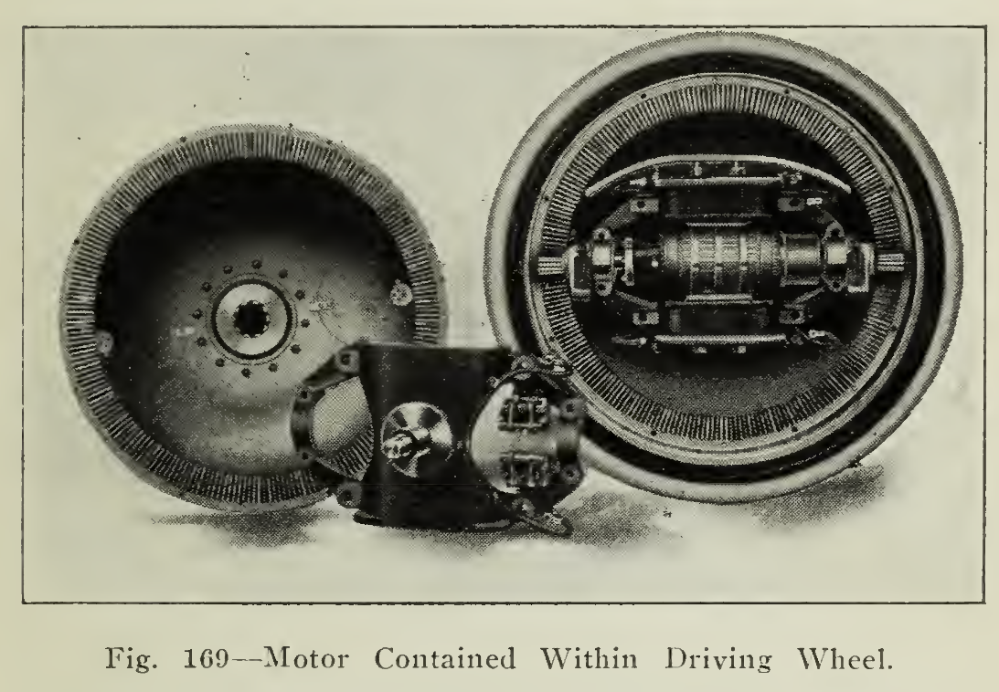
Another type of two or four-wheel drive is accomplished by placing the motors within the metal wheels. As shown in Fig. 169, pinions on each end of the motor shaft engage with the gear racks on the wheel. The motor is set at a slight angle to the plane of the wheel so that the pinions engage with their respective halves of the cog-rack, being free of the other half. By this couple arrangement a single speed reduction is effected without the use of a countershaft.
Sets of either two or four wheels of this construction may be employed and the steering may be either by the forward wheels or through all four wheels for fine maneuvering. When the two forward wheels are used as the tractors, then the rear or drawn wheels may be large steel tired ones such as ordinarily used on horse-drawn vehicles, thereby avoiding the use of rubber tires. The road conditions, together with the service requirements of load and speed, are the determining factors in the specification of the amount of traction necessary and the efficiency of applying it by means of two or four-wheel drive.

Lighting. The electric lighting of motor vehicles is indeed most popular. For the storage battery propelled car it involves only the wiring of the lighting fixtures to the battery through switches placed within convenient reach of the driver. The lighting circuits are fused so injury from accidental short-circuits may be reduced to minimum. The lamps are made in a great variety of styles and shapes and may be placed in positions most suitable to the owner’s requirements. Arrangements are very often made for trouble lamps which may be attached to a receptacle beneath the controller for giving light to inspect damage to tires, loosened nuts or the like.
The meters are, in practically all instances, provided with a lamp of small candle power shaded so as to illuminate the dial without glaring into the eyes of the observer. This light may be lit by pressure on a button underneath the pad of the carpet. Withdrawing the pressure allows the spring to open the circuit. Hitherto the incandescent bulbs used have been of the carbon filament type, but the remarkable developments in the construction of the tungsten lamp have made its use possible for automobile lighting for voltages such as are found in electric vehicle service. The shapes and sizes are suitably designed for use in the different fixtures.
Recently the bayonet candelabra base lamps have been adopted as standard by the Electric Vehicle Association of America. There are a number of vehicles in use at the present time, however, equipped with candelabra screw base and medium screw base sockets so that lamps may be purchased to fit any of these receptacles. New vehicles will be supplied with the standardized product and it is recommended, where alterations in used cars are made, that they also be equipped with the sockets for the candelabra bayonet base lamps.
Wiring. The energy from the storage battery is conducted to the electric motor through insulated wires. Actually, the wiring is from the battery to the controller and thence to the motor, in order that the speed of the motor may be regulated by simply changing the position of the controller handle. In many makes of vehicles a main switch for opening the circuit is included so that there may be no danger of starting the vehicle unexpectedly or its use by those unauthorized. For the latter purpose, the controllers of pleasure vehicles, which may stand unattended for long periods, are furnished with Yale locks, so that the handle cannot be moved until the operator has taken the driving position, inserted and turned the key, which then, cannot be moved until the handle is brought back to the "off" position.
The wiring is done in a very careful manner, giving attention to the use of material of sufficient size to obviate any tendency to heat at normal loads or overloads. The insulation must be good so that there may be no leakage to the frame or between wires. The installation of the wiring must be such that it will be secure in position and not liable to mechanical injury, which would impair its electrical efficiency. To preclude any such possibility, the most approved installations are made by enclosing the leads in metal tubing, proof against injury and moisture. Naturally it is important that all connections be firm and tight so that there may be no sparking or arcing. The use of the electric is not prohibited on docks, piers or in buildings because of the small likelihood of its producing combustion.

The above facts in regard to installation are stated not so much to explain the original safe character of the vehicle, as that is well known, as to emphasize that changes in wiring should be made by competent electricians, so that by no remote possibility can any inflammable material be ignited. Due to improvements and care in this direction, the insurance rate on electric vehicles has decreased and further reductions are being made periodically.
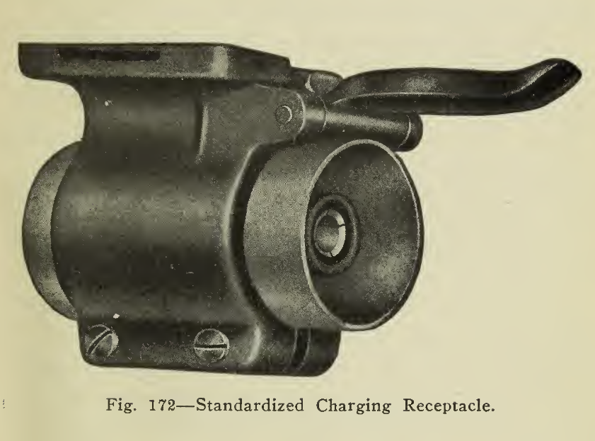
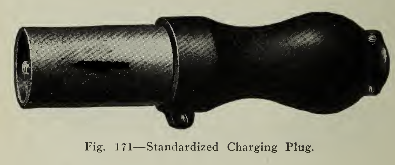
For convenience in making the necessary connections for charging, a charging plug and receptacle is furnished. The receptacle is fastened to the frame of the vehicle and connected to the storage battery. With the controller in the "off" position and all switches open, the charging plug, wired to the charging board, is inserted in the receptacle, making the proper connections quickly and without danger of heating. The charging plug and receptacle standardized by the Electric Vehicle Association of America is shown in Figs. 171 and 172. The inner ring of the receptacle should be connected to the negative pole of the battery and the outer ring to the positive terminal. Likewise, the negative and positive wires of the charging cable should be connected to the inner rod and outer shell of the plug. By following this method it will be possible to place a vehicle on charge f rom any plug without danger of short circuiting or charging the battery in the wrong direction. At the present time there are several styles of plug and receptacle in use, Fig. 170 showing a popular make, but they are more or less defective in strength and there is no uniformity in size or in arrangement of polarity so that interchangeability is not always possible. To obviate this difficulty, the standard adopted as described above has been received very favorably, permitting the car to be run into any charging station for a "Boost."
In addition to the motor used for vehicle propulsion, motors are employed for operating winches, cranes, dumping bodies, pumps and similar devices. These are operated by controllers constructed for the purpose and wired to the battery independently. The same rules of installation apply in these cases as in the regular vehicle wiring.
The wiring of a bell or signal horn is a simple matter, the only precaution necessary being to connect the device across such a number of cells that it will not be damaged by too high a voltage. It is preferable to use a bell connected across the entire series of cells, and as a matter of fact, that is what is done with but few exceptions. The bell is rung either by means of a button in the controller handle or by a floor push, so that in approaching a street intersection or in attempting to pass another vehicle, the signal may be given without perceptible effort on the part of the driver.
MECHANICAL PARTS— THEIR UPKEEP.
It is stated without fear of contradiction that there is no piece of machinery which will perform continuously without care and attention. The electric vehicle is no exception in this respect. However, the number of moving parts is small and they are neither delicate nor complicated. The most important requirement is lubrication. The subject of lubrication is so important to machinery of all kinds that many treatises have been devoted to the exposition of the details of the theory and practice concerned. J"or the purposes of electric automobile operation, however, no theoretical consideration is necessary, the simple rules, "To err on the side of too much rather than too little," and "Add in small amounts often rather than large amounts seldom," being sufficient for all practical purposes.
Vehicles of both the commercial and pleasure types are provided with means for lubrication depending upon the character of the contact surfaces. Oil cups, grease cups and grease boots may be mentioned among these. Wheel bearings are packed with grease, while the treatment prescribed for the controller as previously explained consists in wiping the copper contact with a rag with a little vaseline.
The oils and grease used should in all cases be of good quality, free from acid and grit. If dirt works into any of the bearings, they should be washed out thoroughly in gasoline or kerosene, the old lubricant discarded and uncontaminated used for repacking.
Adjustments are required from time to time, to tighten nuts or screws, chains, brakes, etc., and may be readily made by inspection of the assembly of the parts, with the aid of the instructions of the manufacturer of the particular machine in question. These minor adjustments are practically all that will be required in normal service, barring accident, except for the yearly overhauling which should be done by a competent mechanic familiar with motor vehicle construction.
The object of the yearly overhauling is to renew such parts as may be necessary, such as chains, sprockets, gears, bearings, etc., and submit all parts to examination so that those badly worn may be replaced before an opportunity for breakdown is given. Arrangements should be made for giving this attention as indicated since, with proper care, the vehicle will not fail to give satisfactory service year after year.
It is the intention in the following paragraphs to give a number of hints which have been found useful in the upkeep of the chassis and in rendering its operation continuous.
Steering Gear. The parts of the steering mechanism require proper lubrication, and oil and grease cups are supplied at points conveniently located for effecting the most satisfactory lubrication and ease of access to the operator. These should be gone over daily and the oil and grease cups attended to.
The pinion and sector must be well lubricated with heavy grease. There are many designs of connection between the drag link, the steering arms and the cross bar, but construction will readily indicate the proper method of lubricating the wearing parts. These should be cared for daily. All nuts and joints should be kept in good adjustment to prevent play, as a little lost motion on the steering arms would be magnified many times before reaching the steering wheel.
It has been found, that, if the distance between the rims at the front is from Vs" to 3/16" less than the distance measured between the rims across the rear, the steering will be very much easier, and there will be less tendency for the wheels to depart from a straight line of travel. This toeing in off the front wheels is often called gather. It is important also that, except for the toe in, the wheels run in perfect alignment, as, otherwise, there would be a considerable grinding action upon the tire, which would wear it out rapidly. The adjustment for gather is made by shortening the length of the tie rod between the steering arms. Any nuts which have been loosened to make adjustment should be tightened up securely so that they may not be worked loose, allowing play.
In addition to the grease cups, which lubricate the steering gear proper, it is a good plan to lift the covers, remove the grease and replenish about once every three months.
Chains and Sprockets. Chains and sprockets realize both adjustment and lubrication. Under the of adjustment may be classed the proper alignment of the sprockets. The front and rear must run in perfect alignment at all times, as otherwise the teeth of the sprockets would be damaged and the chains made defective. The chains should run with proper tension so that there is sufficient slack when running that they do not run hard or stretch. They must not be too loose, or they may jump off or slap. The distance or radius rods are provided with means for varying the tension. After altering the distance between sprocket centers by the adjustments of the radius rods, lock nuts, if they are used, should be tightened securely so that the adjustment will be permanent. Sprockets, as a rule, do not last as long as the chains. The wear is evidenced by the teeth becoming hook shaped and causing a whipping or snapping of the chain. This condition naturally imposes unnecessary strain on the latter, and should be avoided.
It is practicable to change the sprockets from side to side of the car, thereby making use of both sides of the sets of teeth. Obviously, when both sets have been worn sufficiently, then new sprockets should be installed. New chains should not be used upon old or much worn sprockets for the reasons explained above.
Chains should be kept in good condition by frequent inspection to see that the lengths of the chains on both sides are equal, in order vent the rear wheels running out of line. The number of links must be employed in both and badly worn parts should not be allowed for any length of time as they will eventually the entire chain. When a rivet or bushing has become loosened from the side plate from some unusual strain, it should be replaced by a new link. Some roller chains are composed of links joined in such a way that each link may be removed without affecting the others, but a great number of chains cannot be dealt with in such a manner, it being difficult to separate the links. The latter type of chain is furnished with a master link, which is serrated at the top edge and has pins a trifle smaller than the others throughout the chain. It is intended for simple and quick removal or replacement. In this type of chain, if it is necessary to replace a worn link, it may be done by inserting a master link.
The lubrication of the chains and sprockets is important and in many cases is practiced in an erroneous manner, namely, by smearing the bearing surface of the chain with grease or oil, which gradually collects dust and grit and causes excessive wear between the rolls and the sprocket teeth. It furnishes no lubrication between the rolls and bushings of the chain, where it is needed most. The following method has been found successful and is recommended by the leading manufacturers:
As often as necessary, such as periods of a month or less, the chain should be removed and soaked ever night in kerosene, after which it should be brushed thoroughly and washed with gasoline to remove any adhering particles of gummed oil or rust. After careful inspection and replacement of worn parts, a shallow pan should be used for containing a heavy melted lubricant in which the entire chain should be submerged. The temperature of the mixture should not be sufficient to draw the temper of the steel, but high enough so that the oil will find its way between the bushings and the rolls or rivets of the chain. Mixtures for this purpose are made up and sold prepared, or a mixture of beef tallow with a small quantity of heavy oil and powdered graphite may be used. In this way the lubricant will penetrate to all parts of the chain. The outside surfaces of the chain should then be wiped dry and the chain may then be replaced and adjusted to the proper tension on the sprockets. It is permissible to apply a light graphite lubricant on the outside of the chain from time to time so that the surfaces of the rolls may run freely over the teeth of the sprockets. Only a small quantity of material should be used for this purpose so that dust and grit may not be collected.
Silent Chains. Silent or link belt chains are usually run completely enclosed in oil when employed in vehicle construction in order that they may be well lubricated at all times and maintained free of dirt. They require very little attention, except for adjustment, after the first 350 or 400 miles and thereafter approximately every 500 miles. A silent chain operates best when it runs slightly looser than would be correct for a leather belt. The lubricant used should be a medium bodied oil of good quality. The joints of the enclosing case should be packed so that the enclosure is tight and does not drop oil.
Countershaft. The countershafts are supported from the frame and have means, such as ball joints or swivel connections with the distance rods, for maintaining the proper relation with the rear axle construction. Adjustments are provided for keeping the shaft properly lined up. Provisions for oiling and grease cups are supplied where there is opportunity for wear, and care should be exercised in oiling and turning up the grease cups daily.
If a brake drum is provided in connection with the countershaft construction, the brake arrangement should be inspected regularly and any loose or worn parts tightened or replaced.
Differential. The differential gear is lubricated by medium bodied grease supplied in the manner adopted in the make of vehicle under consideration, such as by grease cup, or by removing the cover of the housing and filling the lower portion with a sufficient quantity of lubricant. In winter time it will probably be found necessary to supplement the application of grease with a medium bodied oil to secure the proper lubricating quality. Under conditions of unusual commercial service, it is good practice to take down the differential housing every six months, remove the old grease, clean the parts, and replenish with fresh lubricant of the proper consistency.
Bearings. As explained in the description of the various parts of the chassis, it will be noted that every effort is made to reduce the effect of friction between the working surfaces by the use of anti-friction bearings. With the idea of maintenance in mind, bearings may be divided into two classes, adjustable and non-adjustable. The latter require lubrication in small quantities and do not permit of adjustment for wear. To prevent side [)lay after adjustable bearings have been in use for a time, thin spacing washers may be secured from the manufacturer which may be placed between the bearings and the moving parts. For sprockets on counter shafts a sufficient number of washers may be added so that, when the nuts at the end are drawn up tight, the shaft turns hard. Then one washer should be removed and the nut again brought into position, when the shaft should be lined up properly and run freely with very little play.
Front and rear wheel bearings support the entire weight load and vehicle, and must be kept in perfect adjustment and well lubricated. The adjustment consists in having the wheel drawn up on the spindle tight enough so that very little play is felt but allowing wheel to run free. This is usually accomplished by turning up the axle nut until, by grasping two spokes, one at the top and one beneath the hub, no shake can be felt. The nut may then be backed off a half turn and securely locked to prevent its changing position or coming off the spindle. If there is too much shake, the adjusting nut should be tightened, or, if too tight, preventing the wheel from turning freely, then loosened accordingly. On account of the small amount of wear occurring in properly designed non-adjustable annular ball bearings of suitable size for the hub load, these bearings do not require this adjustment, and no provision is made therefor.
The motor bearings, as well as those on the wheels and countershafts, are properly adjusted before shipment from the factory and, under normal conditions, will require cleaning in gasoline and repacking with non-fluid oil only, approximately, every three months to maintain satisfactory operation. Naturally the class of service in which the vehicle is used determines the length of the period between adjustments and thorough overhauling of the wearing parts. Pleasure cars, which are used for only a few miles daily, and heavy trucks, which are driven to their maximum capacity each day in the year, are obviously not in the same class, and so common sense must be made a part of the adjusting and overhauling instructions.
Greases and oils of the best quality without acid or alkaline reaction should be used. Wheel bearings of the roller type should be lubricated by spreading the grease upon the cage holding the rollers. In fact, the hub should be filled with grease which will be taken up by the parts when put into operation, although, at first, it may seem to be excessive. A light grease is suitable for roller bearings.
Bearings in the gear cases, either on countershaft or rear axle, are supplied by means of grease cups, which should be filled regularly once a week and turned down daily.
Springs. Oil cups and grease cups are provided at the points on the springs where friction takes place, and small quantities of oil should be applied and the grease cups given a turn daily. This will prevent bolts and bushings from grinding and wearing out quickly.
The clips should be tightened so that the spring stands firmly on the seat without play. Prominent spring makers recommend inserting a layer of canvas steeped in linseed oil and white lead as an excellent packing to be placed between the spring and its seat on t*he axle. The same authority discourages the use of wood, paper, fibre or leather for this purpose as being more harmful than beneficial. The clips may be taken up at the end of the first and second week of running with full load on, and thereafter at the end of a period of about three months.
Very often friction between the leaves gives rise to disagreeable squeaks and grinding sounds. This may be obviated by lubricating the surfaces between the leaves, by prying them apart and inserting light grease or oil. In performing this operation. care should be taken not to damage the leaf joints. The most satisfactory method recommended by experienced spring makers is to remove the springs from the car about once a year and to disassemble the leaves, washing them in kerosene or turpentine. After boiling in a mixture of tallow and graphite for a few minutes, they may be allowed to dry and be reassembled, sprinkling a small quantity of flake graphite between the leaves. It is said that this treatment will prevent rust for over a period of a year.
Brakes. The braking mechanism requires frequent inspection and adjustment so that there may be no danger of failure at the crucial moment. The care as a rule consists simply in seeing that the normal pressure on the brake pedal produces a firm retarding action. This should be done daily before removing the car from the garage so that, if adjustments are necessary, they may be made before starting out. If the brakes do not hold, inspection will usually show the method of turning up on the turnbuckle or cam springs, for tightening. It sometimes happens that the full travel of the pedal produces sufficient pressure but there is slip between the shoe and drum. This may be due to oil or grease working its way onto the surfaces. It should be washed out thoroughly with gasoline.
Although the adjustments should be made so that the shoes hold tightly, care should be given that the brakes do not bind or drag. They should take hold gradually and bring the car to an easy stop, except in emergency use, as a sudden locking of the brakes may cause stripped tires, skidding or other damage.
In many vehicles the brake pedal is connected with a rod running transversely, suspended from the frame, so that the pressure applied to the brake pedal may be equalized and distributed evenly to the brakes by means of this equalizing bar. Adjustments are provided so that the action of the rods to the brake shoes may be altered, giving equal retardation on each side of the car. This will be very helpful in preventing skidding.
Dragging brakes not only cause unnecessary wear of the brake lining but use up power, thereby reducing speed and mileage. The shoes should ride about free of the drums when the pedal is in the position to prevent any such trouble. Brakes furnished with ratchet locks should be released before the car is started. Some vehicles are furnished with automatic switches which open the circuit when the brakes are locked ; others have a bell ringing contact to indicate that both power and brakes are operative, but differences of opinion exist as to the relative advantages of these means of securing fool-proof construction.