Last Update: March 10, 2018

In the chapter on the subject of Storage Batteries, the words "charging" and "discharging" are used very frequently and refer to the chemical effects produced in the cells of the storage battery by the passage of electric current through them. It is necessary that this charging current must pass through the cells in one and only one direction during the charging operation. For this reason the negative terminal of the series of cells is connected to the negative terminal of the. charging source and the positive terminal to that of the positive source.
In the case of a direct current charging supply these terminals when connected through the proper rheostat will supply the required charging current. With alternating current, however, the terminals are positive and negative one instant, negative and positive the next and this change continues so rapidly that absolutely no charging effect is produced on the battery. If it were not for the apparatus which transforms this alternating current into the current of one direction, direct current, then the latter only would be available for battery charging. Transforming apparatus has been developed which meets every need in this respect with the features of simplicity of operation, safety to battery and user, and efficient results. Thus we have two divisions in the field of charging apparatus; that used for direct current charging and that for transforming or "rectifying" alternating current. The methods used with the accessories necessary will now be taken up under those headings. The actual operations in the charging of vehicle storage batteries are few in number and simple of manipulation, however complex the theory concerning the actions may be. The pleasure derived from the passenger car or the efficient results from the use of the commercial car are gained not by a theoretical study of the inherent parts, but by a working familiarity with the few and simple rules of conduct. It is true of the electric vehicle as it is true of electrical contrivances in general that they are simple, safe and reliable.

DIRECT CURRENT APPARATUS.
Where direct current is available it is in nearly all cases of no volts, 220 volts or 500 to 600 volts. These voltages will vary somewhat, but not considerably.
You remember that for charging, the cells are arranged in series and that the highest charging voltage required at the end of the charge is, with few exceptions, less than no volts. At the beginning of the charge, the required voltage is about 15% less than the final value so that in every case, means must be provided for gradually increasing the voltage from the lowest to the highest value required, in order that the proper charging current may be maintained. Where a no volt supply service is available, the introduction of a variable resistance rheostat in series with the battery is sufficient to accomplish the result.
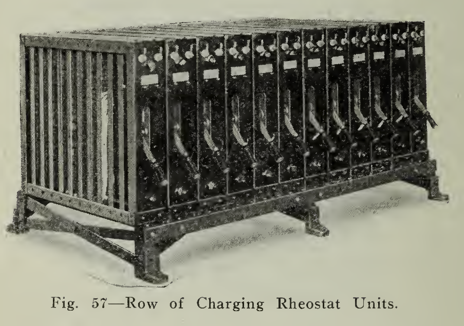
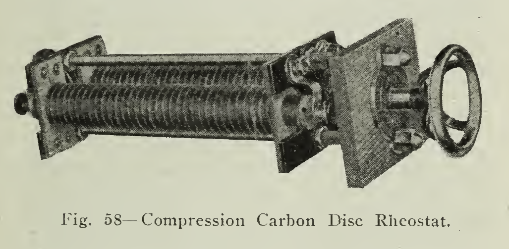
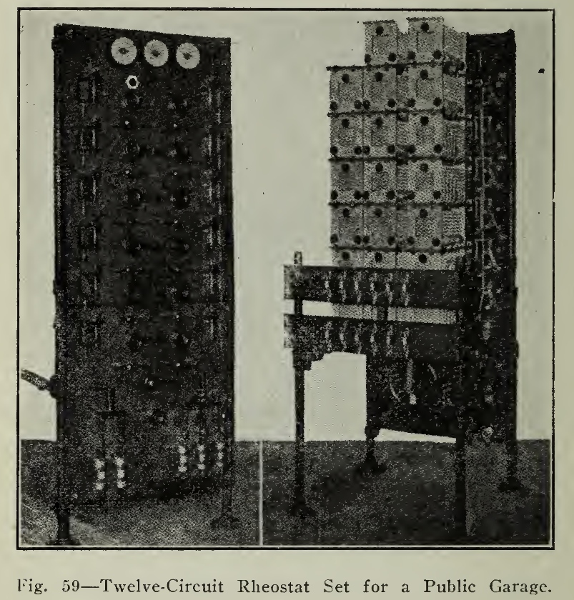
The charging rheostat or variable resistance is of sufficient size to carry the required charging current continuously without undue heating and is constructed so that a movement of the handle or lever lowers or raises the current, which is measured by the ammeter in convenient location for reading. These rheostats as illustrated are produced in many sizes and in several types, representing careful study on the part of the manufacturer, of the needs of the several classes of service, as private small garage, private large garage or small or large public garage. Where the garage is large, many rheostats are needed and while they may be located at one large switchboard or at the individual charging plugs, the operation of each one is simply that described above.
Should the voltage of the supply source be 220 volts then it will be necessary to use a rheostat with much greater resistance than for a no volt circuit. The loss in the rheostat is more than twice, as much in this case, but is unavoidable excepting where a motor generator set may be used as described on page 173.
There are localities where neither no volts, 220 volts D. C. (direct current) or alternating current is available, but where 500-600 volts D. C. may be had from an electric trolley line. As the loss of energy, dissipated in heat in the resistance, is so large in proportion to that effecting chemical change in the battery, this application is to be recommended only in extreme cases, such as temporary, emergency or other charging applications to which there is no other alternative. It should be clearly understood that the above statement refers to the charging of a vehicle battery from the 500 volt circuit through resistance. If the use is to be permanent then it would be advisable to use a motor generator set (page 173). This is especially true where a number of vehicles are to be regularly charged as the efficiency of the total installation will rise with the number of cars charged at the same time.
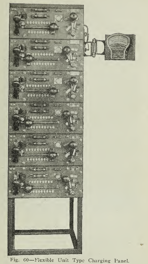

The rheostat is usually mounted upon an insulating slab of slate or marble and connected through a fused switch and circuit breaker, protective devices and instruments (voltmeter, ammeter and watt-hour meter), to the battery. (Fig. 63.) The circuit breaker is an electrical device which automatically discontinues the passage of current when it reaches too high a value. An adjusting screw fixes the value at which the flow will be interrupted. The setting is arranged to prevent excessively large current passing through the battery and ruining it by overcharge, overheating or both. The switch which cuts off all current to the battery is fused so that additional safety from too high current or short circuit may be provided. If the circuit breaker opens or “trips," it is necessary only to reduce the current and close it, but when a fuse “blows” it is necessary to insert a new one after locating the trouble. For this reason the breaker should be set to trip below the capacity of the fuse so that this inconvenience may be avoided without impairing the protection. The current passes directly through the ammeter which gives the rate at which the charging is done.

The voltmeter records the voltage across the battery terminals; the readings of voltage are those referred to in the tables (pages 49 & 131). The watt-hour meter is usually on the service side of the main switch in small installations and is not an indicating meter as are the above, but is a recording instrument giving the additive result. The difference in reading between the end and beginning of charge is the amount of energy in kilowatt-hours used. This number multiplied by the price per kilowatt-hour is the cost of the energy and can be regularly and easily checked. In many garages, one of these meters is provided for each vehicle charged, so that its energy consumption may be measured individually. The protective devices mentioned in addition to those described are an under-load release (low current) cut-out (Fig. 63), maximum voltage cut-out (2) and solenoid switch (3). The low current release, automatically opens the circuit if the current falls to a predetermined minimum. This prevents the battery from discharging into the line should the voltage of the supply circuit fall below that of the battery. The maximum voltage cut-out automatically opens the circuit when the voltage of the battery reaches the voltage at which the cut-out is set to operate. In this way the charge may be automatically discontinued when completed, by setting the cut-out to trip when the battery in question has come up to the required voltage. This action would have to be dispensed with during the period of bi-weekly overcharge so that all cells can be brought up to healthy condition. The solenoid switch "makes" or "breaks” the circuit by closing or opening. It is automatic in action, remaining closed and keeping the charging circuit closed when the main switch is closed, but opening and remaining open when that switch is opened until it is again closed. This device is usually accompanied by the overload breaker (Fig. 63), so that protection is afforded to the battery under all conditions with a minimum of attention. The operation of these devices in connection with a rheostat will now be given.
Having the battery arranged for charge (page 37), all switches open and the resistance all "in” (usually with the handle to the left or at the bottom position), the charging plug is inserted in the receptacle on the vehicle. The knife switch is then closed and the lever moved to the right to the second or third contact segment (depending on the particular make of rheostat), while bringing the plunger on the low current cut-out up into position, allowing the flow of current to energize the main line solenoid switch permitting the flow of current to the battery through the ammeter and resistance. The lever is then moved further to the right until the current is at the proper rate as indicated by the ammeter.

Should there be an interruption in the supply circuit, or the voltage of the line drop below that of the battery tending to cause it to discharge into the line, then the low current cut-out will release its plunger causing the current to cease in the solenoid switch, demagnetizing it and opening the circuit. Should the charging current reach too high a value then the overload circuit breaker will become sufficiently energized to "trip" the solenoid switch, opening the circuit. Finally, if the charge progress without interruption, when the voltage reaches that at which the maximum voltage cut-out is adjusted to operate, it will “trip” and discontinue the charge, eliminating any danger of overcharge but allowing a full charge. Some devices are arranged so as to prevent the operator placing the battery on charge except by moving the lever to the extreme left and beginning with a small current; others return the lever to the starting position as soon as the circuit is opened.

It is possible to control the current automatically by reducing the resistance in series with the battery step by step as the counter voltage of the cells increases. Fig. 65 shows a device designed to maintain a constant current throughout the period of charge. This is accomplished by means of the pointer of the meter and the relay and solenoid on the lower part of the panel. As the battery voltage increases with the charge, the current is decreased, the meter pointer traveling to the left. Adjustment made by a set screw on the instrument, permits the relay of the lower right hand corner to be energized, when the minimum current desired is reached. The energizing of the relay causes it to close the contacts of the solenoid circuit, allowing the latter to draw its plunger in, advancing the regulator one step. Each step thus cut-out increases the current rate about five amperes. This process continues until either the charge is complete or all the resistance is cut-out. When the latter condition has been reached the relay at the top of the board causes the charging circuit to be opened. This rheostat is designed to maintain a uniform charging rate and is more applicable to the charging of Edison batteries than lead batteries, which are favored by a tapering (decreasing current) charge.
The Ampere-hour Meter is described on page 192 and has come into very extended use for vehicle charging purposes. In nearly all cases it is mounted directly upon the vehicle, but the connections are arranged so that when the pointer makes the contact, when the charging is completed, the circuit breaker upon the charging panel is "tripped" and the circuit is opened. This affords a simple means of automatic charging as the battery may be put on charge at a starting rate such that the average charging current will be the same as though attendance was given at the board. This method is described on page 64. In this connection it should not be understood that no attention is required during the charging as in nearly all cases the more attention the better would be the results but a little time at the right time will obviate, in the majority of cases, the difficulties encountered.
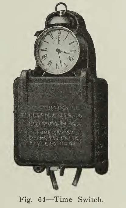
A device known as an "automatic time switch cut-out" (Fig. 64) is frequently used for terminating the charging of a battery and is reliable and safe in accomplishing this result if properly installed. The device is merely a clock which can be set to "trip" open the circuit at a specific time in much the same manner as the alarm clock awakens the slumberer. It is to be recommended where the requirements do not exceed these qualifications. The only disadvantage is that it relies upon the intelligence of the operator to predetermine the amount of charge necessary before setting the dial. However, with a given battery, several carefully watched charges, checking up by voltage and specific gravity readings, will readily determine the approximate length of time needed to bring the battery into a fully charged condition.
A maximum voltage cut-out (Fig. 63) has been mentioned above and its effectiveness in operation depends upon the assumption that the voltage of the supply circuit remains constant or practically so while the battery voltage gradually increases to the limit set on the cut-out. The end of charge of lead battery is determined not by the voltage reaching a certain voltage but by its reaching and maintaining a certain maximum voltage. The latter will vary with the temperature, the specific gravity and the condition of the plates but for a given battery the change will probably be not very great from time to time so that by taking an occasional check reading with a hydrometer and voltmeter the cut-out can be made not only very useful but also reliable. In such cases where the exact conditions are not definitely known as with a new battery or when charged only infrequently at a garage, it is not well to depend upon a voltage cutout as either under-charge or serious and harmful over-charge with attendant heating might result and entirely ruin the battery.
In the previous paragraphs practically all of the devices commonly used in vehicle battery charging have been explained. This does not mean that the battery cannot be charged unless accompanied by the use of such devices, but that they are very effective and convenient means of accomplishing the desired result with the least effort. To summarize therefore, to charge from a direct current source it is necessary to have a suitable rheostat placed in series with a battery for controlling the current as well as a voltmeter and ammeter to measure these quantities. The voltmeter and ammeter may either be a combined instrument having the two scales or two separate instruments. When located on the vehicle the combined instrument (volt-ammeter) is used. Where the ampere-hour meter is located on the vehicle then the volt-ammeter is not usually found necessary and is located on the charging panel instead.
ALTERNATING CURRENT APPARATUS.
In order to make an alternating current available for storage battery charging it must be changed or “rectified" into current which is of one direction, direct current. When it has been thus treated its effects upon the battery are identical with those of the direct current supplied from the power station. When alternating current is rectified by means of a device which produces a current which is uniform in direction but pulsating in pressure the effects upon the storage battery are just the same as if the current were of constant and uniform voltage. The devices for changing or converting alternating current into direct current for vehicle charging are, known as Motor Generators; Rotary Converters and Mercury Arc Rectifiers.
The motor generator (Fig. 76) effects the transformation in a very simple manner. The alternating current supply is used to operate the alternating current motor to which is coupled a direct current generator. The generator in this case gives a direct current of the voltage required and acts in all respects similar to the generating apparatus used in the power stations. It may be varied in speed, voltage and in current output so as to conform to the requirements of the garage, be the number of vehicle batteries small or large. The Rotary Converter makes use of the same principle as the motor generator with the exception that the motor and generator are combined into one machine having a common field and armature. At one end of the armature the commutator for supplying the direct current is placed while at the other end the slip-rings of the alternating current motor are situated. The Rotary Converter or Motor Generator is used where a considerable number of batteries are to be charged at one time. Should but a few vehicles require charging at one time or if arrangements are such that a few vehicles may be charged at intervals, then neither of these machines would give efficient results and the combination would best be effected by use of mercury arc rectifiers.
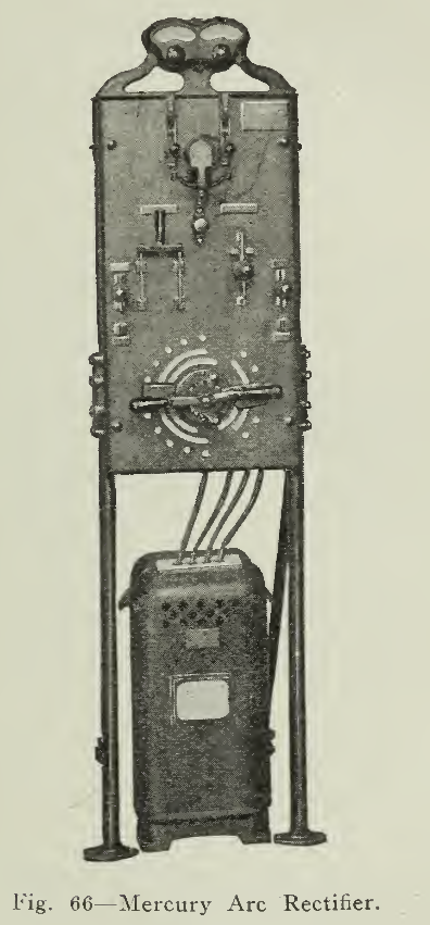
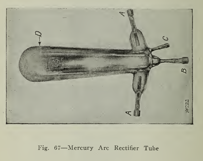
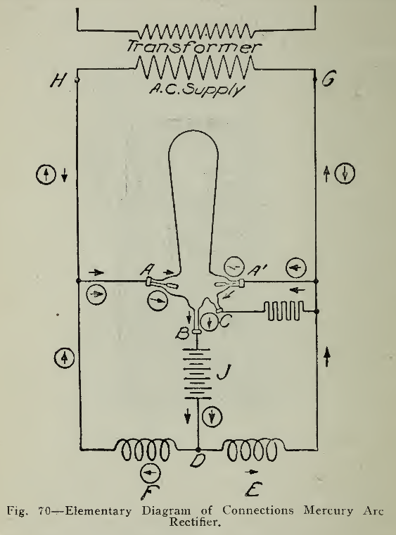
The mercury arc rectifier is probably the most widely used piece of charging apparatus as the majority of central stations supply only alternating current. Its action is reliable and continuous while its operation is very simple. Any number of batteries may be charged efficiently and the equipment can be increased from time to time as the demands require. For a private small garage a single mercury arc rectifier unit is used while in a large garage a number of units of large capacity operate with similar results. An individual unit (Fig. 66) consists of a slate panel upon which are placed the switches, measuring instruments and mercury tube, and an enclosed coil on the floor beneath it. The leads from the alternating supply circuit are brought to the panel and connected to the apparatus through a fused switch. A cable from the vehicle is connected through a circuit breaker to the converting apparatus. The apparatus which effects the change from alternating current to direct current consists of a large glass bulb of peculiar shape as shown in (Fig. 67) and a number of coils of wire over an iron core known as reactances shown diagrammatically in (Fig. 68, E. & F).
The rectifier tube is an exhausted glass vessel in which are two graphite electrodes (anodes "AA") and one mercury cathode ("B"). Each anode is connected to a separate side of the alternating current supply, and also through one-half of the main reactance to the, negative side of the load. The cathode is connected to the positive side. There is also a small starting electrode ("C") connected to one side of the alternating current circuit through resistance, and used for starting the arc. When the rectifier tube is rocked, so as to form and break a mercury bridge between the cathode "B" and the starting anode "C" a slight arc is formed. This starts what is known as the "excitation" of the tube. and the, cathode begins supplying ionized mercury vapor. This condition of excitation can be kept up only as long as there is current flowing toward the cathode.
If the direction of supply voltage is reversed, so that the formerly negative electrode, or cathode, becomes positive with the reversal of the alternating current circuit, the current ceases to flow, since, in order to flow in the opposite direction, it would require the formation of a new cathode, which can be accomplished only by special means. Therefore, in the rectifier tube, the current must always flow toward the cathode which is kept in a state of excitation by the current itself.
Such a tube would cease to operate on alternating current voltage after one-half the cycle, if some means were, not provided to maintain the flow of current continuously toward the cathode.

The maintenance of the current flow is accomplished by the main reactance. As the current alternates, first one anode and then the other becomes positive, the current flowing from the positive anode through the mercury vapor, toward the cathode, thence through the battery, or other load, and back through one-half of the, main reactance to the opposite side of the alternating current supply circuit.
As the current flows through the main reactance, it charges it, and while the value of the alternating wave, is decreasing, reversing and increasing, the reactance discharges, thus maintaining the arc until the voltage reaches the value required to maintain the current against the counter e.m.f. of the load, and reducing the fluctuations in the, direct current. In this way, a true continuous current is produced with very little loss in transformation.
The manipulation of the mercury arc rectifier is very simple and requires a minimum of attention although it must be understood that in battery charging attention of the right kind is required. Exactly what such attention should be is explained under the separate headings.
As mentioned above the rectifier unit (Fig. 66) consists of the panel with the controlling devices upon it and the reactance coil encased in iron situated on the floor beneath it. Without going into details in regard to the construction of the reactance coil, suffice it to say that the connections are made and the terminals brought out and lettered for ordinary connections to the proper points on the panel. Excepting in cases where vehicles of different numbers of cells are to be charged from the same rectifier at different times no changes are necessary in the wiring of the reactance to the panel. Where necessary they may be very simply accomplished by following the manufacturer's directions. The panel of the rectifier unit which holds the meters and controlling devices, is usually of slate mounted upon pipe support. All wiring connections are on the back of the board so that on the front there may be no confusion to the inexperienced. Al main "A. C." line switch (Fig. 66) and circuit breaker, ammeter and voltmeter in the "D. C." circuit, are usually found on the panel. The handle or dial switch shown at the bottom of the panel is connected to a small reactance coil mounted on the rear of the panel for making finer regulation of the voltage applied to the battery. A tube mounted in a convenient holder at the back of the panel is connected by a rod extending through the board to a small knob on its face so that the tube may be rocked to and fro in starting its operation. This leaves but one switch upon the board unexplained. It is a special switch for starting which is thrown in an upward position while rocking the tube and after the arc has been formed is released and is held in the lower position by a spring.
The connections established in the operation of this switch supply the resistance and load necessary for maintaining the arc in the tube before the battery is put on charge.
It is not necessary that the panel be provided with instruments, but if the vehicle is not provided with volt-ammeter then the board should be. In all cases it is well to have the panel thus provided as the vehicle instruments being subject to shocks and jars may not be in good condition at all times.
To begin a charge at the proper starting rate, for the battery in question, inspection should be made of the panel to see that the switches are in the proper starting position, that is, open, and with the regulating handles in the lowest position then close the alternating current line switch and circuit breaker. While rocking the tube gently so that the mercury bridge between the cathode and starting anode may be broken, place the starting switch in the starting position. The arc will then be formed and maintained in the tube after which the regulating switches may be adjusted to give the proper charging current. As the charge progresses, the adjustments of current are made by simply altering the position of the regulating switches without discontinuing the operation of the rectifier until the end of the charge. If the tube “goes out” or does not maintain the arc when the starting switch is released into the operating position, the operation should be tried again with the setting of the regulating switch several points higher. As there are two regulating handles, one being steps of regulation of greater size than the other, adjustment should be made with the smaller or fine regulating switch until it has reached its maximum when it should be reduced to its lowest position and steps of the coarse regulating switch added and final adjustment made with the fine regulating switch. By this means any voltage supplied by the rectifier from its minimum to maximum capacity may be obtained.
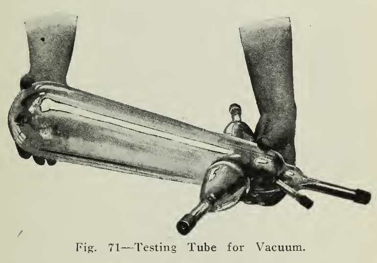
Should on the other hand the tube fail to maintain the arc when thrown over into the operating position and an increase of voltage described does not effect the desired results, then the trouble is elsewhere. Inspection should be made of the connections on the back of the board to see if all are secure and if this does not produce the desired results then the tube should be disconnected, carefully removed from its holder and held in the position shown in (Fig. 71). Giving care not to allow the mercury to run into the side arm, the lower end should be raised (Fig. 72) until the mercury rises in the large end. This operation should be, done slowly so that the mercury will run in a small stream separating into drops. If the tube is in good condition the drops will come together with a sharp metallic click, but if the tube should be defective, by reason of a poor vacuum, then the stream will be relatively slow to run and a dull thud will be heard instead of the characteristic metallic click. Should this test show that the vacuum is impaired, it will be necessary to communicate with the manufacturer with regard to a new tube, but if the tube is found to be in good condition then the services of a competent electrician will be required.


For the operation of a single vehicle, a rectifier set (Fig. 73), is designed to charge the number of cells in the particular battery in the vehicle and is not adapted for charging much greater or less number. Should it be desired to charge batteries having different numbers of cells, then a rectifier unit which can be operated over a wide voltage range will be most suitable. In fact, if the owner is likely to purchase a new car at any time it would be wise to install the latter or standard set so that there need be no difficulty at the time of change of cars.
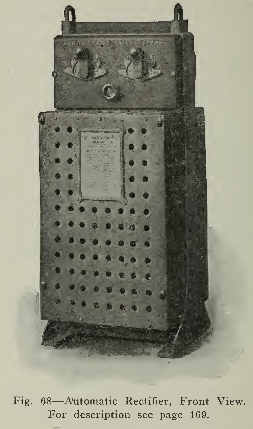
In figure 68 is shown another make of mercury rectifier which is entirely enclosed in a single unit. The transformer reactance, bulb, etc., are mounted on a cast iron frame (Fig. 71) and completely enclosed by metal covers. No live parts whatever are exposed, which eliminates all danger of shocks to the operator, or to children. Large and small step dial switches make it easy to charge any number of cells within a wide range, without change of commutators. A magnet energized from a small auxiliary transformer is provided to tilt the bulb and automatically restart the outfit whenever the current has been interrupted by line voltage fluctuations. A relay energized by the charging current disconnects the tilting outfit as soon as the arc starts up in the bulb, and reconnects it whenever the current fails for any reason. This is particularly important for private garage installations, where charging is done at night without attendance, as it ensures a full charge in the morning. For public garages where attendance is available, a similar outfit is available arranged for hand starting only. Its outside appearance is the same as in the case of the automatic outfit. The dial switches on both outfits permit adjusting the current without putting out the arc. The design of the transformer and reactance is such that no change of adjustment is ordinarily necessary during a charge.
A circuit breaker on the automatic outfit, and a fuse on the hand-starting outfit, give protection against overload or reversed polarities.
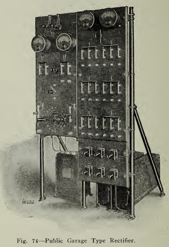
(Figure 75) shows a rectifier outfit that has been simplified down to its essential elements in order to till the demand for an outfit of low first cost. The transformer and reactance have been combined in one coil and control is by means of link connections instead of dial switches. Hand starting only is provided. This outfit is suitable for use where only a single vehicle is to be charged, and is designed to cover a comparatively narrow range of cells including only the most commonly used batteries. As no changes of adjustment are ordinarily needed during a charge, the lack of dial switches causes little inconvenience.
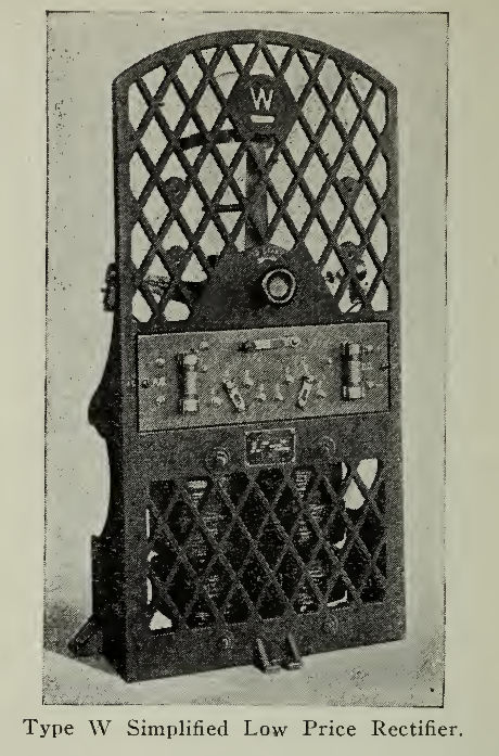
For garages handling a number of vehicles, whether of the pleasure or commercial type, the rectifier units (Fig. 74), will prove very satisfactory, flexible and efficient. If but one car is to be charged at a time, but one rectifier unit need be run while on the other hand if a number of batteries are to be charged then the required number of rectifier units to supply this demand may be added. This feature does not obtain with either the motor generator set or the rotary converter as either of these machines operate as a unit irrespective of the number of batteries charging. This flexibility of the mercury arc rectifier is a very important feature, not only affecting the efficiency of the garage apparatus in operation, but allowing the establishment to add equipment from time to time, providing, of course, that the estimated demands at the beginning or after a reasonable interval of time of operation do not require the installation of a motor generator set.
It requires a certain dissipation of energy to maintain the arc in a mercury tube which is evidenced in the form of heat and a small quantity of light. The voltage required to maintain this arc is about 15 volts and is practically constant for all currents which the tube will stand, thus the efficiency of the rectifier depends upon the total voltage delivered to the battery or in other words, the greater the number of cells charged within the limits of the rectifier the greater will be the efficiency. In practice this efficiency increases from 70% at 60 volts DC. to 80% at 175 volts DC.
As to the life of the tube, a good tube should last at least 600 hours, but many have run 6000 hours or more. This is practically the only part of the apparatus which will wear out under normal average use.

The mercury arc rectifier is usually operated from a single-phase alternating current circuit, or one phase of a three-phase circuit. The frequency upon which the mercury arc rectifier will operate may be from 25 to 140 cycles with slight changes in the apparatus. The voltage impressed is either no or 220 volts. Higher voltages than these may be easily reduced to these values through suitable transformers. The maximum current which a single tube is capable of giving is 50 amperes at continuous operation. Larger currents than this are obtained by arranging a number of rectifiers in parallel by means of an auxiliary control panel.
MOTOR GENERATORS.
The motor generator has two applications in vehicle charging, namely, changing direct current of a high voltage to no volts or less (Fig. 76) and for changing alternating current to direct current of suitable voltage (Fig. 77). In speaking of direct current voltages, 220 volts and over, it was recommended that it was very much more economical to install a motor generator set than to charge through a resistance on account of the great loss in the rheostat. Where charging is temporary or infrequent this condition will of course not apply, but in nearly all cases it will be found upon calculation that it is more efficient to use the set. The efficiency will increase directly with the number of vehicles charged at the same time from the generator. It is often found advisable to operate the motor generator when the load is heavy, that is, a considerable number of cars charging and to shut it down and charge from a few rectifiers when the number of cars is not sufficient to justify the operation of the motor generator with economy.

Rotary Converter. This piece of machinery produces the results effected by the rectifier and the motor generator set, but usually requires a larger number of cars to be charged for efficient results.

LINCOLN CHARGER.
The apparatus used for charging electric cars in the usual private garage is divided in one sense into two classes:
First, apparatus on which the variation of voltage of supply current will affect the charging rate and those which do not.
The first class is represented by the mercury arc rectifier and the rotary converter.
The second class is represented by all classes of motor generator sets in which a motor of the induction type is used for driving the generator which charges the battery.
The apparatus is divided into these two classes for the following reason:
Lead batteries must be charged at the end of the charge at a very low rate. If this is not done, destructive gassing and heating occur. Since the internal resistance of a lead battery is small and small variations of voltage impressed on the battery terminals will make a large variation in charging rate, therefore, with whatever type of apparatus is used for charging, if the voltage impressed on the battery terminals is varied even slightly it will make a large difference in the rate at which the charging is done. The reason for this is that the line voltage in any district, particularly, in the residential and outlying districts is subject to considerable variation on account of variation in load. Unfortunately this variation is in the wrong direction for safety of the battery. The voltage starts in lowest when the load is heaviest and is highest when the load is lightest. The battery in the usual private garage is charged during the night, the charging being completed early in the morning.
In the usual residential district the voltage is somewhat lower from 8 to lo o'clock than it is from 4 to 5 o’clock the following morning when the charge is generally completed. This means that with a setting which will give a proper finishing rate at g o’clock in the evening, there will be too high a finishing rate if the battery finishes up at 5 o’clock in the morning.
This variation is not nearly as large in the very large cities as it is in some of the smaller towns but it is present to a certain extent in all cases. This has caused the battery builders and consequently the car builders to seek some type of charging apparatus whose charging rate will not be dependent upon the line voltage. This has brought to the front the use of a motor generator set for this purpose on account of the fact that the line voltage has no effect whatsoever on the charging rate. A variation of 25% above or below normal in line voltage will make absolutely no difference in the finishing rate of the charge. This has meant that particularly in the last few years, there has been a very large application of motor generator sets to charging work especially where skilled attendance is not present. The slightly lower electrical efficiency is more than compensated for by the enormously less battery depreciation and charger depreciation, since a well built motor generator set will operate on this charging work indefinitely without appreciable wear.
As an example of this fact, let us take a standard equipment and assume conditions which are more or less standard all over the country. Suppose we take a battery equipment of 40 amperes, thirteen plates. This will take under normal conditions 80 amperes to charge when the battery is in good condition and the car is in good condition also. 180 ampere hours input will give a full charge in this battery. Data from a large number of batteries which have been in service show that under average conditions when a battery is charged with a rectifier, that 7,500 miles is its life. There are a number of battery builders willing to guarantee that if charged with a non-gassing, non-heating schedule which a properly built motor generator set will give, that this battery life will be doubled. Let us then assume that the cost of power is 4c per k.w.h. that the k.w. hrs. input to charge with the rectifier will be 21 1/2, with the properly built charger. The battery cost of an outfit similar to the one above will be approximate $250, then our comparative cost to charge will be as follows:
Current cost with rectifier, 86c or 1.08c per mile. Tube depreciation on a basis of $22.50 as the cost of tube and 300 hours the guaranteed life of the tube, .6c per mile. Battery depreciation on a basis of $250 as the cost of the battery, 7,500 miles as its life, 3.3c per mile. Total cost per mile, 5.07c.
Now let us consider its cost under the conditions of being charged on a non-gassing, non-heating schedule as would be given by the Lincoln charger.
Current cost, 96c per charge or 1.2c per mile. Charger depreciation, negligible, as there is no tube or other such devices to depreciate. Battery depreciation on basis of 15,000 miles, 1 2/3c per mile. Total cost, 2.87c per mile.
This covers the reason why a charger of this type is supplanting the use of the rectifier. A description of this outfit will be about as follows:
The scheme that the manufacturer had in mind in making it was to come as close to a constant potential charge as is practical and still keep the size and efficiency of the charger up to the highest possible point. By so doing it was possible to get an outfit which will start off at a rate of 40 to 60 amperes and finish up at a rate of 8 amperes, or less. This will give a charge which is absolutely non-gassing and non-heating and which will keep the battery in the very best condition. No matter what happens on the line, whether the voltage rises or falls, whether it is interrupted entirely for short periods, the charge is made complete and is always on a non-gassing, non-heating schedule. The details of construction have been carried out so that the set is built together, the armature mounted in ball bearings and the whole set connected and wired to the switch-box so that all that is necessary to do when the apparatus is received by the user is to screw the switch-box to the wall, insert the plug into the car, connect the leads from the supply line to the two lugs in the box, close the switch and then the charge will be completed in from eight to twelve hours and the charge also will be perfect. If it is left on less than 8 hours, the charge is not quite complete, and if it is left on more than 14 hours no damage is done, in fact, this could be left on a week at a time without any damage whatever to the battery or the apparatus.
These reasons have determined the application of this apparatus to charging rather than the mercury arc rectifier.
Mechanical and Synchronous Rectifiers. Considerable experimenting has been made upon mechanical, chemical and synchronous rectifiers, but up to the present time they are available only for rectifying currents of small amperage, not being adapted to the charging of electric vehicles, especially in numbers.
Boosting. Hastening a charge or "Boosting" is very often a feature of value in electric vehicle operation, and if there is any likelihood of high rate charges being necessary, the charging apparatus installed should be capable of maintaining the required current without undue heating. Not only the instruments and resistance should be of capacity, sufficient to operate under these conditions, but all wiring on the charging panels and vehicles as well.
Temperature is a limiting feature in storage battery charging. The current is limited only by the maximum allowable temperature (page 50) and the gassing. For lead batteries the gassing should be kept a minimum at all times; Edison cells are not affected by the gassing, temperature only requiring consideration. The necessity for boosting is practically eliminated in the small private garage, but in public garages is a very important feature and it is safe to say that current in excess of two hundred amperes from a charging plug could be utilized for this purpose, in maintaining vehicle operation during adverse weather and road conditions. For this reason this item should be considered in the choice of apparatus for an installation.
The word "Booster" is used in another connection, and designates a direct current generator of low voltage but of ample current carrying capacity. It sometimes happens that the direct current voltage supplied is no volts and that 6o cells of Edison battery or 44 cells of lead battery, requiring no volts, are to be charged. Should the line voltage be less, however, or it be required to increase the rate by increasing the voltage then the booster would increase the voltage the desired amount, carrying the current so dealt with through its armature. This use is resorted to in some cases when the capacity of the existing apparatus is found inadequate in the above respect, rather than install a new equipment. Excepting for this use in vehicle battery charging there is little occasion for the use of a booster, its application being confined in most cases to large lighting battery installations.
ISOLATED PLANTS
As a general rule it may be said that, except in very few cases, the isolated plant cannot compete with the central station in supplying current for vehicle charging. This applies both to the price and flexibility of the service rendered. There are peculiar conditions existing in some localities which do however merit the use of a steam or hydro-carbon engine and generator.
Should no power be available from a central station, as obtains with some farms, country homes, hotels or factories, then the problem resolves itself into the choice of the proper size of electric outfit, as electric light and power for kindred devices are demanded in most cases. Usually a 115-125-volt generating set, gasoline or oil engine driven, will be found thoroughly satisfactory and economical, providing that apparatus designed for this use is installed. Makeshift combinations of engine and generator, ill suited to combined operation, can hardly be recommended as the little attention given, and the probable absence of expert service in time of need, would make the results not only unsatisfactory, but more costly in the long run. The capacity of the equipment should be determined with regard to the future requirements as well as the present needs. It is impossible to lay down a fixed rule as no two problems will be identical. The manufacturers of recognized equipments may be relied upon to effect a simple and economical solution and will gladly offer their services.
Charging Stations. Communication with the central station companies supplying electricity in the larger cities of the country has shown that there is at present an abundant supply of charging stations, and that the number is constantly increasing at a very rapid rate. The names and locations of these stations change somewhat from time to time so that a list of the 700 and more public charging stations distributed over the United States is not appended. Definite information as to the names and locations of these stations may be readily secured by communicating directly with the central station company supplying the district concerned. In practically all cases the electric lighting and power companies have these lists, supplemented with road maps and other attractive information of local character. The Electric Vehicle Section, N. E. L. A., maintains a bureau for the dissemination of such knowledge, and communication will bring forth the desired information.
The number of public charging stations given above includes only those which operate for public garaging of electric vehicles The large number of private commercial installations, such as breweries, express companies, department stores, grocers, etc., owning fleets of vehicles garaged in their own installations, are not included The number of electric passenger vehicles is increasing very steadily, and as the small private garage with charging set adjacent to the residence is attractive and convenient, the number of private garages for pleasure cars will be found to be several times in excess of the number given for public stations.
When the electric is to be charged at a station other than its regular garage, a plug should be carried so that the necessary wiring arrangements may be conveniently secured, and the capacity and charging rates of the battery should be recorded and carried for convenient reference.


