Last Update: March 10, 2018

The storage battery is the part of the electric vehicle which holds the energy necessary for propulsion. It is the heart of the vehicle and so should receive proper care and attention. It consists of a number of cells or units grouped in trays according to the size and character of the vehicle. Each "cell" consists of a jar containing a number of plates properly connected, spaced with separators and immersed in a solution or electrolyte.
There are two classes of storage batteries enjoying commercial representation. These are, the lead-sulphuric-acid and nickel-iron-alkaline cells. A description of each of these important divisions will be given in order that the instructions covering their care and operation may be more easily and fully understood.
Historically the lead battery is the oldest form of storage cell used to any extent for vehicle service. The name lead-acid battery is given because the plates of the cells are made of lead and the solution is sulphuric-acid and water.
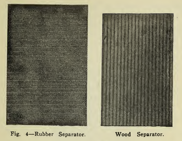
The plates of a lead battery are of two kinds, positive (+) and negative (-) (Figs, 1 and 2), arranged alternately in the cell, there usually being an excess of one negative plate so that all surfaces of the positive plates may be active. The plates of batteries used in vehicle service are of two general sizes, 4 3/4" X 8 5/8" or 5 3/4" x 8 5/8" and from 1/8" to 3/8" in thickness, depending upon the requirements as explained later. By means of lead connecting straps (Fig. 3) all the positive plates in each cell are joined into what is known as a positive group; all the negative plates similarly into a negative group. These two groups, with the separators (Fig. 4) for keeping the positive plates from making contact with the negative plates, form an element (Fig. 5). A hard rubber jar contains this element, immersed in a solution of sulphuric acid called electrolyte, the complete unit being called a cell (Fig. 6). A hard rubber cover is usually sealed over the top of the cell to reduce evaporation and Spraying. The sealing compound is easily applied or removed when slightly heated.
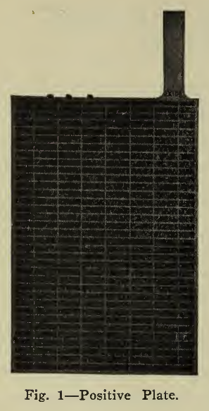
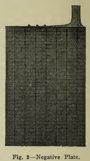
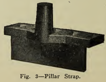
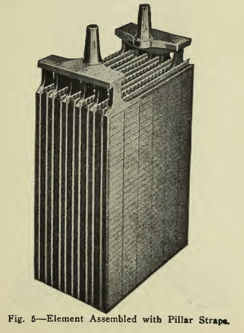
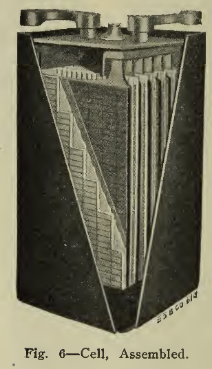
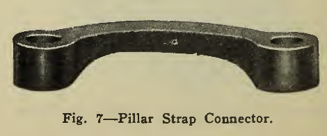
The connecting straps, besides connecting the plates of a group, have a pole or terminal, extending slightly above the top of the jar, so that the positive group of one cell may be connected to the negative, group of the next cell by a lead connector (Fig- 7).
By connecting the negative pole of each cell to the positive pole of the next, the cells are said to be connected in series; all Positives together and all Negatives together, respectively, "in parallel." If the total number of cells is divided into two or more parts, of cells in series, and the divisions together in parallel then the connection is. said to be "series-parallel.” In vehicle practice, the series grouping is used with very few exceptions.
A storage battery does not store electrical energy but holds the energy chemically. The electrical power produces chemical changes in the cells which are known as charging, and when the chemical energy is converted to electrical energy, then the reactions taking place in the cell are called discharging. These phenomena are very interesting and explain not only the reasons for the details of construction but the method of operation most conducive to satisfactory and efficient results.
When the battery is said to be charged then the lead of the positive plate is of chocolate brown color and is called lead peroxide while the negative plate IS gray colored and consists of metallic lead in a form called spongy lead. This action is caused by the passage of current from the positive to the negative plate through the electrolyte. When the current is reversed by connecting the positive and negative poles through external resistance then the reaction known as discharge takes place, and the lead peroxide of the positive plate is converted to lead -sulphate of lighter brown color and the negative plate from spongy lead to lead sulphate, light slate in color. Pure lead sulphate is white, but as it is mixed with the lead peroxide and sponge lead, in the plates according to the extent to which the reactions of charge or discharge have taken place, the color of the plate will depend on how far the plate has been charged or discharged. In other words, the more the discharge the lighter the color and the more complete the charge the darker. These colors, however, are relative and give definite indications only to those experienced.
The action described above takes place over the surface of the plates and extends only very slightly within when sheets of lead are used as the plates. This layer or film of chemically active lead is therefore called active material. During that part of the cycle when the cell is discharged, the active material consists partially of lead sulphate. Sulphation is the normal condition of the plates on discharge and is caused by the sulphuric acid going into the plates. Inasmuch as the specific gravity of the electrolyte decreases in proportion to the increase of sulphation in the plates, low specific gravity is the indication of the extent of sulphation or of the extent of discharge. This indication is very important since in charging when the sulphate is removed from the plates, returned to the electrolyte, the battery is charged and the rise in specific gravity shows its progress. When the specific gravity has remained stationary for some time then no more sulphate is being transferred to the solution, the useful chemical action is completed, and the charging should be discontinued.
Lead sulphate is hard so that a discharged negative feels harder than a charged one, because the surface is covered with it. If the current is not supplied long enough to reduce all of the sulphate then it hardens and requires still more current to reduce it on the following charge. This is undercharging. If the plates be allowed to stand long in a discharged condition, then the hardening of the sulphate requires an excessive amount of charging beyond that normally needed, or overcharging, to bring the plates back to healthy condition. It is necessary to do this as the pores of the plate would otherwise be clogged, and less surface be useful.
When the current has charged the plates sufficiently for the greater part of lead sulphate to be decomposed then the further passage of current is spent not in useful chemical action (as that is complete), but in breaking up the electrolyte into hydrogen and oxygen gas. When thus liberated the gaseous particles are said to be nascent, and are particularly violent in their action. They are formed during the entire charge and act on the sulphate The action of the hydrogen reduces the sulphate leaving spongy lead on the negative plate and the oxygen oxidizes the sulphate of the positive plate to lead peroxide. These actions being completed, the same amount of current continues to produce the same amount of gaseous particles, which, finding no sulphate to reduce or oxidize, force their way through the active material and out of the solution as gas. The more violent and rapid the gassing, the greater is the tendency for small particles of active material to be forced off of the plate surface to fall to the bottom of the cell as sediment. As the coherence of the positive active material is considerably less than that of the negative, excessive gassing deteriorates the positive plate most rapidly. From this it will be seen that the gassing should be kept a minimum and is accomplished by reducing the current gradually until the plates are fully charged. The values of current used in charging are called charging rates and those in discharge, discharge rates. They will be explained in detail on page 25.
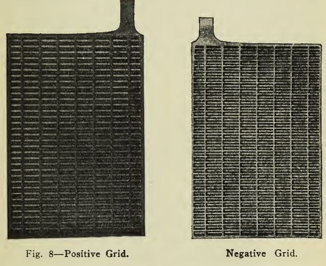
The discussion in the preceding lines assumed only two lead sheets as plates to begin with. In vehicle service, however, a minimum of weight with a maximum of capacity during life is a very important feature, so that instead of making use of only a thin layer of active material on a thick sheet of lead which is inherently heavy, the active material is formed chemically and firmly pressed into a light but strong network or frame of lead alloy. This frame or grid (Fig. 8), is characterized by the necessity for strength to hold the greatest amount of active material firmly in the least space and to withstand the stresses of expansion and contraction as well as to present good conductivity to the passage of the electric current. This type of plate, invented by Faure, is the Pasted plate, and is practically standard for vehicle use. Both positive and negative plates are made in this manner.
Another form of positive plate is one having slotted hard rubber tubes as the containers of the active material. These tubes have a cylindrical lead alloy core fastened to the grid at top and bottom and are surrounded by lead peroxide held by the casing in order that the shedding of active material may be reduced and the effective surface increased.
The separators which correctly space the plates are of two kinds, thin sheets of perforated hard rubber and thin ribbed wood, chemically treated to remove injurious impurities. One side of this wood separator is flat, pressing against the negative plate while the other side presses the rubber sheet against the surface of the positive plate. The separators serve the purpose of allowing circulation of the electrolyte and escape of gas, while preventing contact of the plates which would cause a short circuit in the cells. Through vibration, the separators are liable to work loose and float up from the bottom of the plates, exposing them to contact. To prevent this, extensions from the under side of the plate straps, or hard rubber blocks are made use of in holding the separators in position.
The containing jars are composed of hard rubber compound, of dimensions that will snugly contain the assembled elements, leaving a space of from i" to 3" under the bottom of the plates to collect sediment and about 1 1/2" above the tops of the plates to allow sufficient height of electrolyte without slopping over. The tops of the jars are fitted with covers, having openings for adding pure water (to replace evaporation) and are provided with vent plugs to allow the escape of gas. These covers are generally sealed on with a compound to avoid sloppage, reduce evaporation and prevent introduction of foreign material. Two supporting ribs or bridges cast integral with the bottom of the jar, are provided to support the element and provide space for the collection of sediment without allowing it to come in contact with the plates.
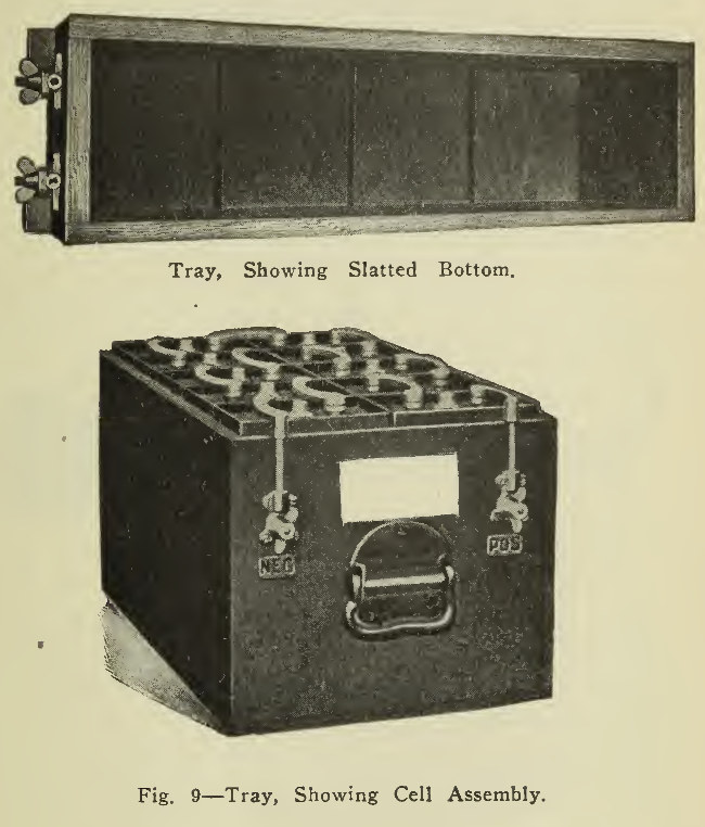
A tray (Fig. 9) is used to hold a number of cells rigidly in the vehicle and protect the containing jars from damage as well as admit of convenient handling in assembly or removal from the battery compartment. These trays are built of hard wood treated with acid-resisting paint. Handles for handling and connectors for making secure connections to the wiring of the vehicle arc placed on the outside of the tray ends. A name plate is usually attached at a conspicuous point for ready reference.
The process of attaching the plates to the connecting straps to form the positive and negative groups, and the connectors to the poles, is known as lead burning and consists in the application of a flame of sufficient heat to weld or melt the lead parts into one. This is similar to soldering, except that in this case no flux is used and the flame is applied to the parts directly. For temporary repairs soldering may be applied, but not otherwise. This process is described in detail on page 95.
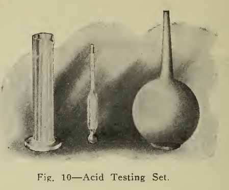
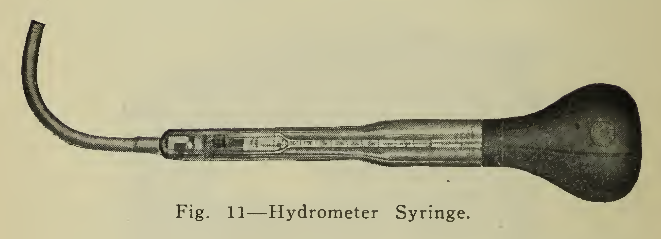
The specific gravity or relative density of a solution is determined by the use of an acid testing set (Fig. lo) or a hydrometer syringe (Fig. ii). The hydrometer syringe is most convenient as it permits a reading of specific gravity to be taken quickly in any cell of the battery. The syringe with rubber bulb allows electrolyte to be withdrawn from the cell into the tube in which the hydrometer floats. The hydrometer reading may be thus observed, after which the electrolyte is returned to the cell without spilling or contamination.
CHARGE AND DISCHARGE RATES.
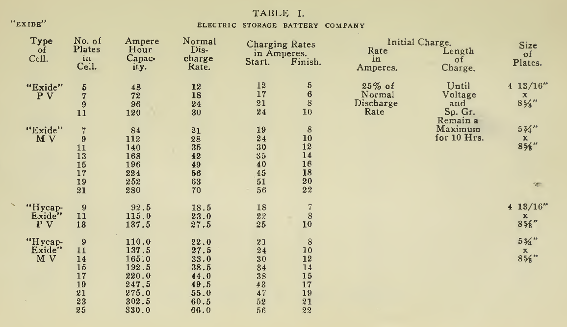
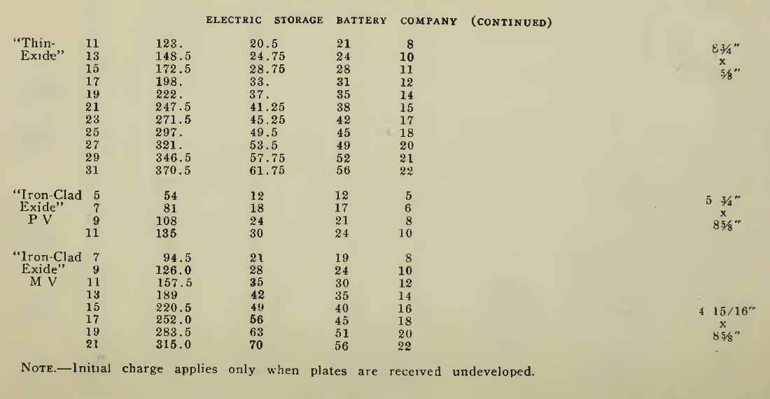
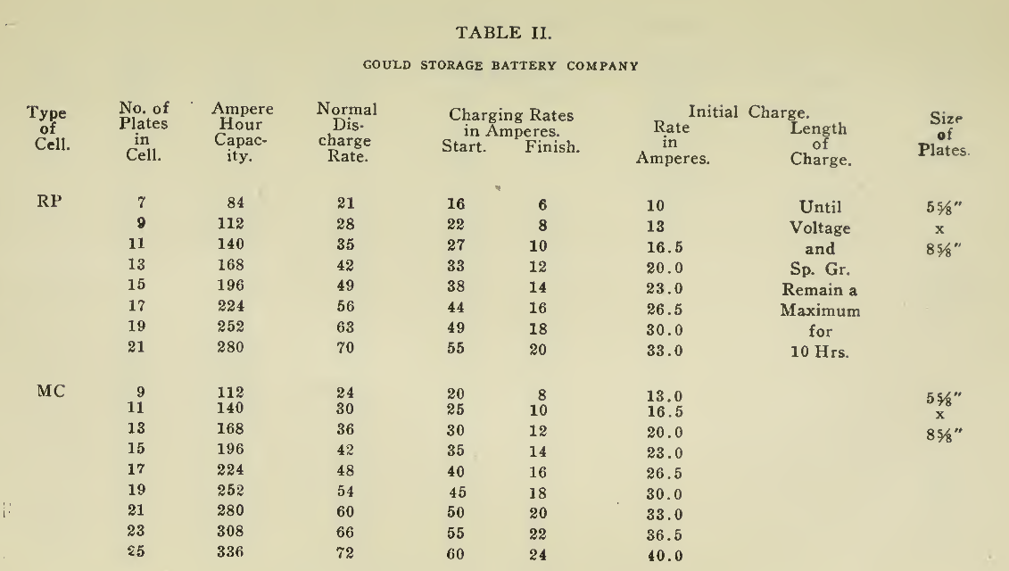
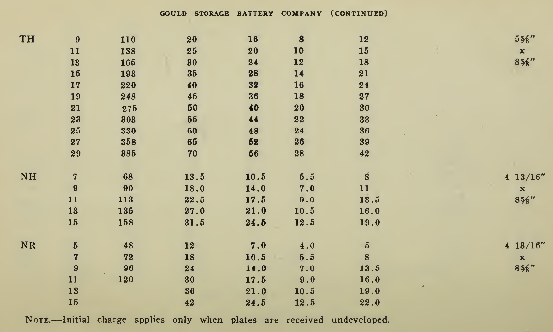
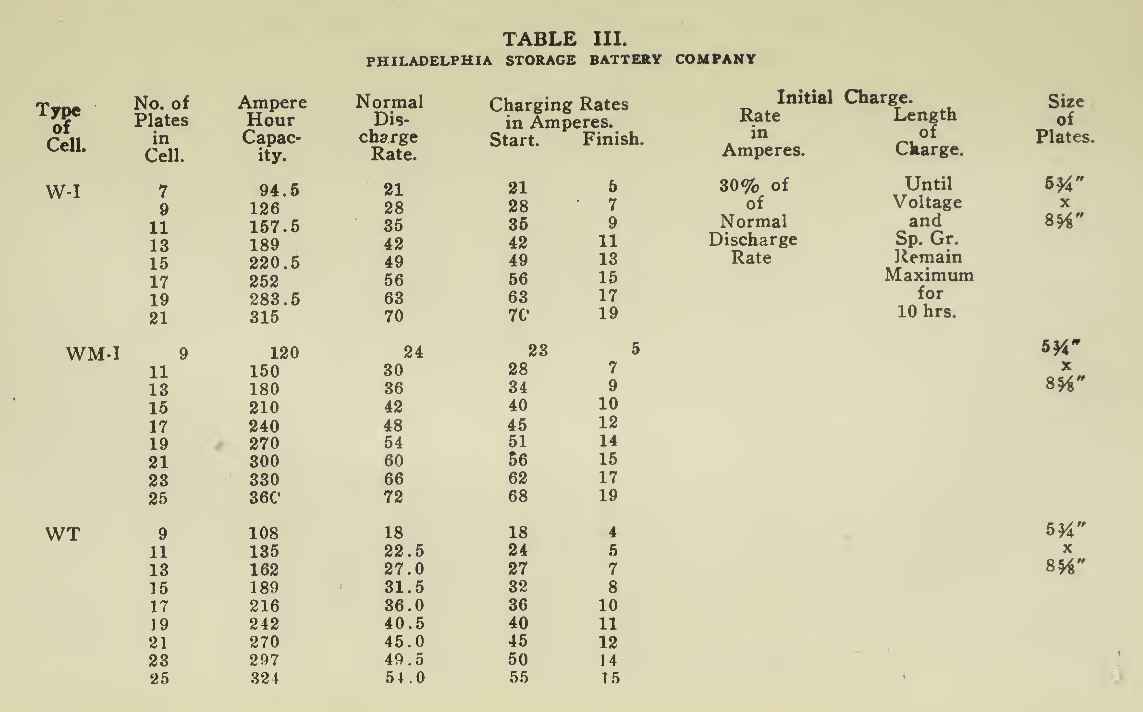
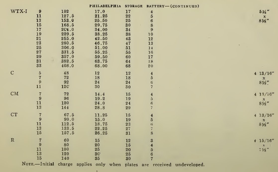
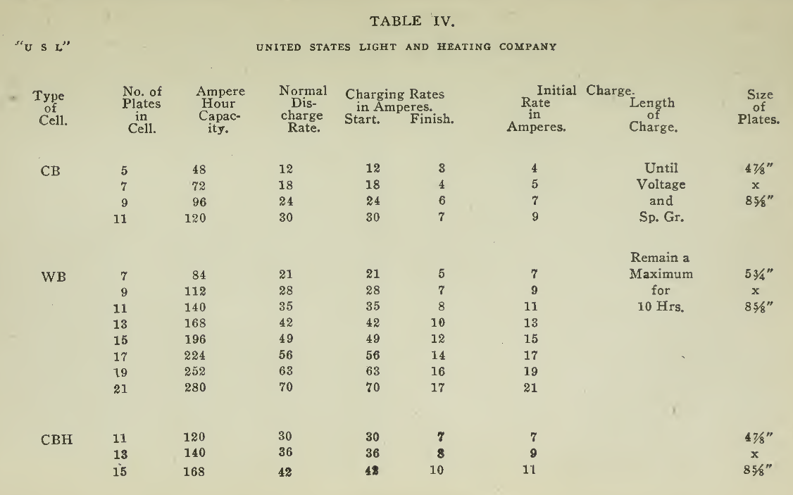
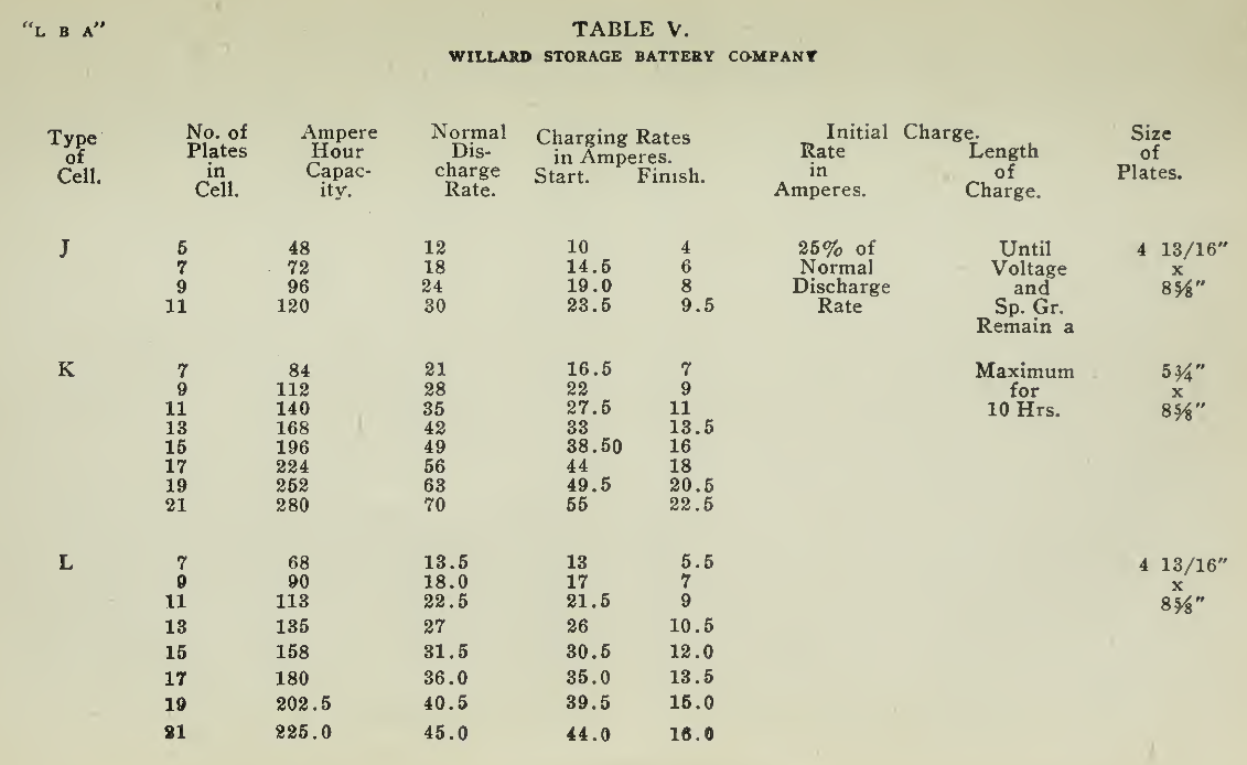
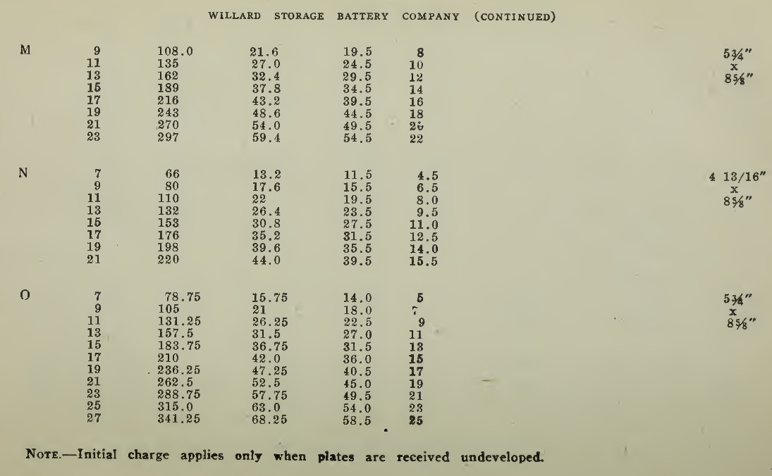
The "Charging Rate" is the current measured in amperes, used to effect the chemical changes in the cell known as “Charging." “Starting Rate" and “Finishing Rate" are the values of current employed at the beginning and finishing periods.
The “Discharge Rate" is the value of current in amperes at which energy is furnished by the battery. This rate may be constant for a number of hours as on a laboratory test or may vary considerably as when furnishing current to the motor. The length of time in hours during which the battery will deliver its catalogue discharge rate before reaching 1.7 volts per cell, multiplied by the discharge rate in amperes, gives the "Discharge Capacity" of the battery in ampere-hours.
In charging, since the storage battery is not 100% efficient in operation, it is necessary to add from 5 to 15% more ampere-hours of charge than are recovered in ampere-hours of discharge. As it is not possible to charge continuously at the same rate as that at which the battery may be discharged, several hours more are needed to completely charge than are required to discharge at the catalogue discharge rate. The catalogue charge and discharge rate established by the manufacturers are neither maximum nor minimum values for the cells in question but average or moderate figures which experience and test have shown to be acceptable for all ordinary variations of vehicle service.

CARE OF STORAGE BATTERIES.
General Instructions APPLICABLE TO ALL STORAGE BATTERIES
Considerable may be and has been written on the subject of care and operation of storage batteries and the whole matter may be summed up in a few words by saying the few things that it is necessary to do and the correct times for doing them. There are certain requisites in the care which cannot be made light of and yet which require a very small amount of time. In the operation of the battery, proper charging is of first consideration since the energy taken from the battery must be replenished for continued operation.
Charging. In charging Storage Batteries, be the make or design what it may, a direct current supply must be used. If alternating current only is available then means must be had for transforming or converting it into direct current. This is a subject which has received careful attention by the manufacturers and will be taken up in detail in Chapter VI.
The common practice in the arrangement of electric vehicle batteries for charging is to connect all the cells in series, the adjacent positive and negative poles being connected, leaving a positive terminal (pole) at one end and a negative terminal at the other unconnected. These are connected respectively to the positive and the negative wires of the charging circuit in order that the charging current may be forced into the battery through each cell in the same and correct direction, positive plate to negative through the solution. This rule cannot be varied as injury to the battery, with perhaps ruin, will follow. The procedure just described is actually taken care of in the wiring of the vehicle, as received from the manufacturer so that when the trays are installed in the positions indicated and the cells of one tray connected in series to those of the next, it remains only to attach the leads of the vehicle wiring to the end cells.
These are carried to a charging receptacle situated on the frame of the vehicle convenient of access. This receptacle is constructed for rigid holding of the charging plug, to which are connected the wires from the charging source. The plugs and receptacles used at present are relatively simple and serve the purpose of connecting the charging source to the vehicle battery, preventing accidental or careless contact of the wires of opposite polarity which would cause a short circuit.
At the present time the different forms of charging plug and receptacle supplied by the individual manufacturers of electric vehicles necessitate the public garage carrying an assortment of these to handle such different makes of vehicle as may require charging, either regularly or transient. This inconvenience is obviated by the use of the charging plug adopted as standard by the Electric Vehicle Association of America.
Automatic means for regulating the charging operation are widely used and are explained In the Chapter on “Charging Apparatus."
Ventilation. The battery should be ventilated as much as possible during charging to carry off the gases liberated, hydrogen and oxygen. To this end the battery compartments should be opened.
Naked Flame. The gases liberated, hydrogen and oxygen, will combine explosively when ignited, so that great care should be exercised to keep the compartment free of a naked flame, especially while the cells are gassing or immediately thereafter. An electric light should always be used for inspection.
Electrolyte. Before commencing a charge, the height of the solution should be adjusted to a level, 1/2” above the tops of the plates, using distilled water only for this purpose, never electrolyte. How often it will be necessary to add water will depend upon the amount of charging, but will be about once a week, more or less. Where it is especially desired to use water, other than distilled, it is best to send a one quart sample to the manufacturer before running the risk of ruining the battery due to impurities in the water. Electrolyte should only be added where necessitated by sloppage or leakage and then as explained in detail (page 73). Evaporation removes only water and so nothing but water should be added to compensate. It should be stored in clean carboys which have been used for no other purpose and distinctly labelled.
Voltage. The voltage required at the Battery Terminals in order to force the current through the battery is given in the tables on pages 49 and 131 for batteries of a number of cells of both lead and nickel-iron types.
Inasmuch as voltage during charge is considerably higher than that during discharge, the lamps, bell, signal horn or other such devices should not be left on or operated during the charging operations, as the increased voltage will in most cases be sufficient to burn them out. These devices are designed to operate during the discharge only, there being practically no reason for their use at other times.
Temperature. During the charging or discharging operations, described below, the temperature of the battery should at all times be kept below 110° F. The temperature should be measured in those cells near the center of the battery and if there is a tendency to overheat the charging rate should be reduced or if necessary the charging discontinued until the temperature has fallen below the allowable limit. Practically no difficulty will be experienced during discharge except under most extraordinary circumstances.
Charging: Manipulation. Having determined the proper charging rate and the length of time for the charge, the charging apparatus should be put in position for the beginning of the charge, with all switches open. The controller is then placed in the off position, or as demanded in the vehicle in question, some controllers having a special charging position, or notch. With the total resistance of the rheostat in circuit, the charging plug is placed in the receptacle and the switches closed. The ammeter will show a low value of current, which will increase to the necessary amount as the rheostat handle is revolved. As the charging progresses and the current either increases or decreases the manipulation of the resistance by the movement of the rheostat handle will increase or decrease the charging rate as desired. Usually a movement of the rheostat to the right increases while a movement to the left decreases the current. When the battery is fully charged the operation should be followed in the reverse direction, that is, put all the resistance in, decreasing the current, by moving back the rheostat handle before opening all the switches and removing the charging plug. Making a rule of this practice will avoid short circuits, and burning of contacts.
Discharging. In vehicle batteries the discharging of the cells consists in allowing the current to flow in the reverse direction from that of charge, through a motor which converts the electrical energy into mechanical energy for motion. The amount of current supplied to the motor is regulated by the controller so that starting, stopping, reversing or running at the different speeds may be accomplished with little effort on the part of the driver and without injury to the motor, battery or other parts.
Charging: Out of the Vehicle. When it necessary either for test, after repairs, or with reserve batteries to charge them out of the vehicle on a bench, then the operation, familiarly known as a bench charging or discharging, is identical with that described for the battery in the vehicle in nearly all particulars. It admits of ready access to each of the cells during the entire charge and discharge and enables the operator to make complete and full readings of voltage, specific gravity, temperature and such other inspection, as may be required, upon each cell of the number. As this treatment can best be given by placing the battery in a garage where the necessary apparatus and skill is to be had, the details will be given in section II., page 49, devoted to garage practice.


