Last Update: March 10, 2018

(Arranged alphabetically)
Electric Storage Battery Company, Philadelphia, Pa., “Exide”
This company produces four distinct types of battery for this purpose, known respectively under the trade-names of "Exide," "Hycap-Exide," “Thin-Exide" and "Iron-Clad-Exide."
The standard Exide plate was the first of the four and is still in very wide use throughout the country, giving satisfaction where it is used in the proper application. The "Hycap-Exide” plate is of the same size in length and breadth but is not as thick, so that more plates may be assembled in the same size jar as used for the "Exide" plate and is intended for use where the daily mileage consumed is greater than that afforded by the “Exide." ,The daily mileage procured from the “Hycap-Exide" will be greater than that from the “Exide" but the total mileage under average conditions will be approximately the same. The type of grid used in these plates, shown in (Fig. 8 , p. 21) is known as the “staggered bar type" and serves as a very effective container for the active material which receives special treatment, the result of many years of experimenting.
The “Exide" and “Hycap-Exide" type plates are each made in two sizes known as "MV" and "PV." The length and thickness of the "PV" plate is identical with that of the “MV” plate, of the corresponding type, but the width is reduced from 5%" to 4 13/16" or a reduction of about 16%. The "PV" type plate is used where the output required is somewhat less than that required from the “MV” type plate.
The “Thin-Exide” plate has the same general dimensions in length and width as the preceding types but being thinner the manufacturers state that even greater mileage may be secured upon a single charge of the battery than from the “Hycap-Exide” plate. The total mileage, however, during the life of the plates as compared with either the “Hycap-Exide” or “Exide” plates should be about the same. The statement is also made that where the daily mileage given by either the "Hycap-Exide" or "Thin-Exide" plates is not required, the "Exide" should be used and will be found more satisfactory from the standpoint of service and economy.
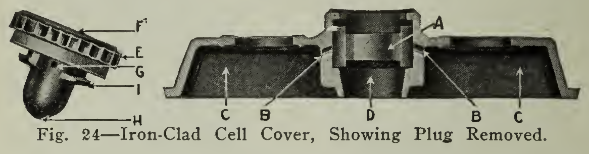
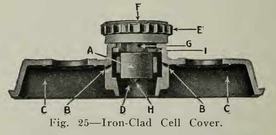
Within the past few years this Company has introduced and placed large quantities of cells in service equipped with a positive plate known as an "Iron-Clad-Exide."
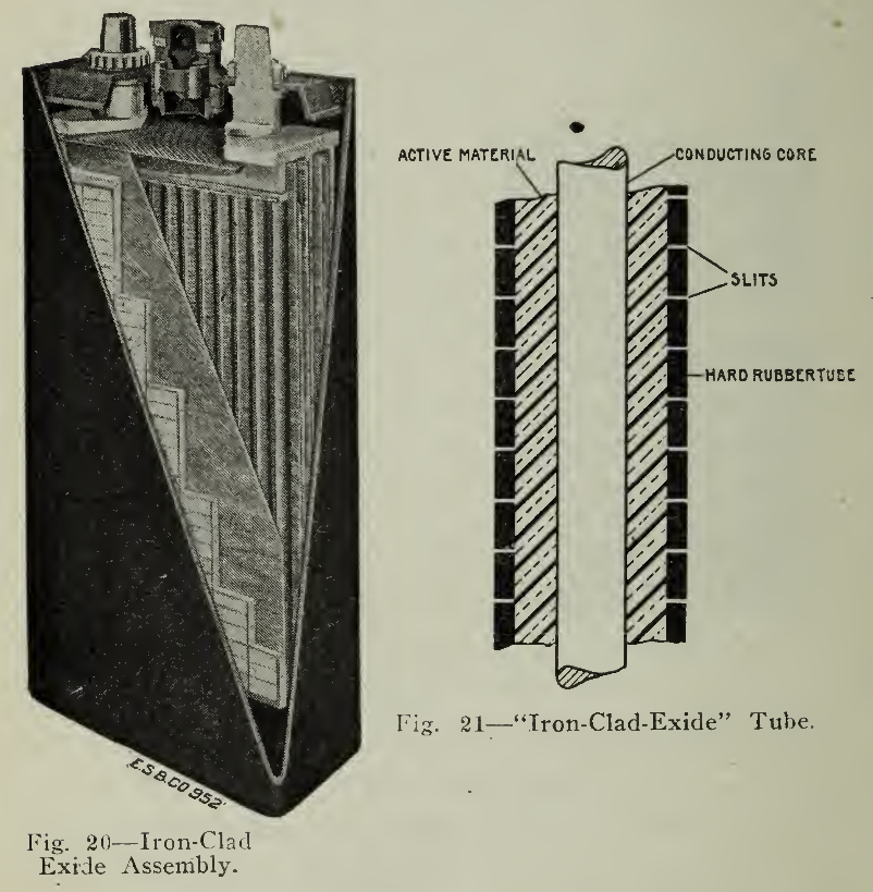
Fig. 21 - "Iron-Clad Exide" tube
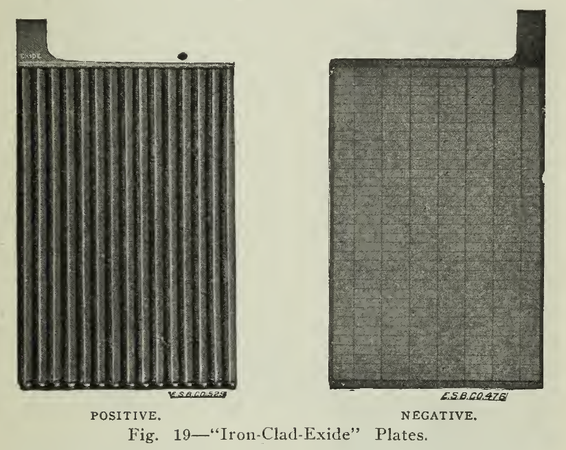
This plate known also as the "Pencil Positive" Plate is shown in (Fig. 19). The manufacturers find that in this plate greater effective surface is secured for the active material, giving greater capacity than the "Exide" plate and that by this design a life of two or three times that of the "Exide" is obtained.
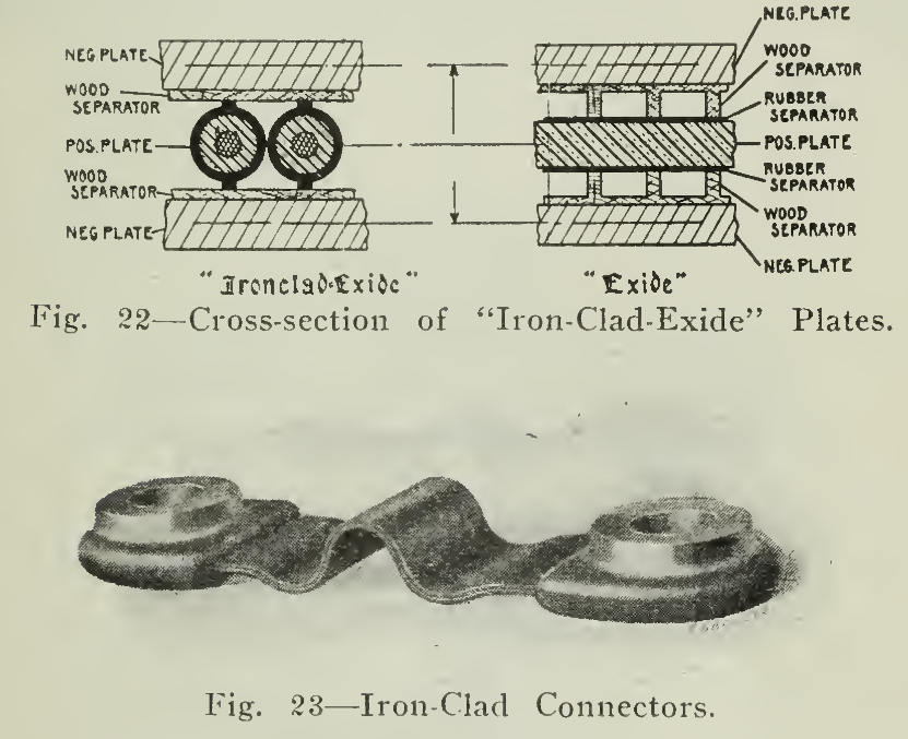
Fig. 21 - Iron-Clad Connectors
The active material is held in the rubber (Fig. 21) in such a manner that ordinary wear and tear will not dislodge it with the same rapidity that will obtain in the "Exide" so that the accumulation of sediment will be very much less rapid and the useful life of the plates will have been secured before it is necessary to take the cells apart for cleaning. The negative plate has the same characteristics as those found in the "Exide" cell but in this case is made slightly heavier in order to compensate for the increased life of the positive plates without necessitating a renewal before the life of the positive plates have been exhausted. In other words, it is intended that the life of both positive and negative plates shall be equal. In the assembly of the plates a perforated hard rubber sheet separator is not required. A thin wood separator especially treated and cross grained is used, however.
A flexible connection shown in connection with the description of the cell is another feature characteristic of the "Iron-Clad" assembly. Frequent reference has been made to the disconnecting of cells in the preceding pages and the method given, that of drilling through the strap to the pillar post.
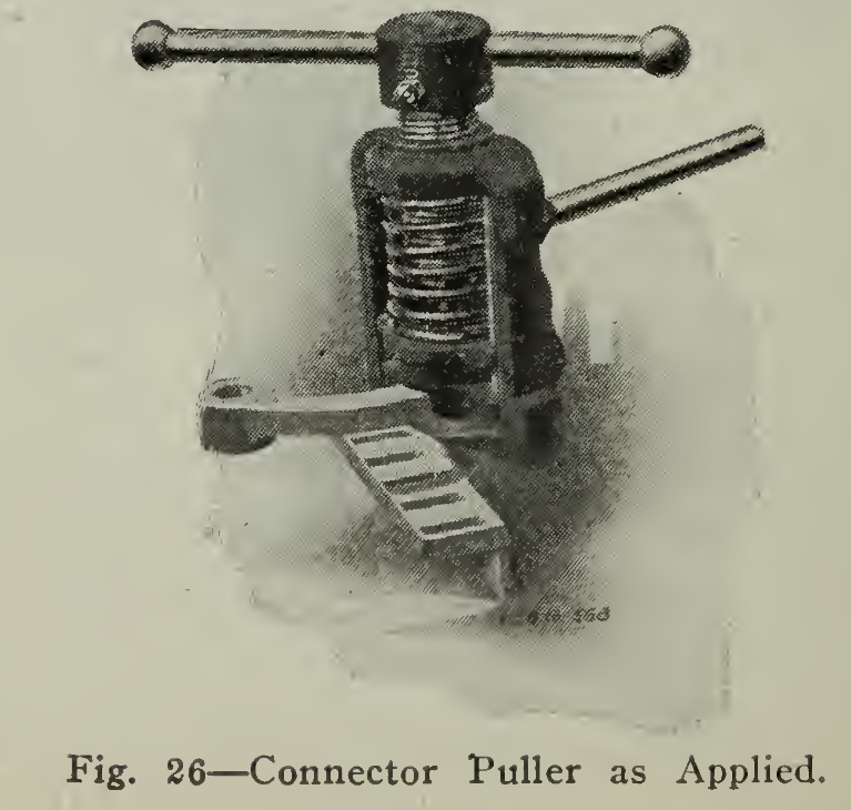
A connector puller produced by this Company is designed to accomplish this result in a simple and effective manner. It is placed around the connection as shown in (Fig. 26) and shears the connector free from the post without injury to either, so that the connector may be again used.
Gould Storage Battery Company, New York City
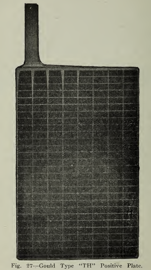
The plates produced by this Company use the staggered bar grid which has been found very satisfactory and efficient in vehicle battery practice. Numerous experiments and years of service have proven this statement a fact. The claim is made by the manufacturers that the active material in the positive plates is compounded in a manner designed by a special process for hardening without entailing loss in capacity, the principle being the use in service of a layer of active material of sufficient thickness to give the necessary capacity but not thick enough to increase the precipitation of sediment (Fig. 27). Practically, this works out well for, as the active material falls off through wear, the hard material in the center is softened at approximately the same rate, and thus maintains a uniformly thick layer of active material and uniform capacity during the life of the plate.
From the above it will be seen that great effort has been expended in the many details involved in producing plates of such a character that the all important features of resistance to wear, retention of capacity and ability to withstand severe service conditions, such as dislodging of active material through overcharge or damage due to jarring, may be secured. The negative plates are constructed with the same ideas in mind, and an effort is made to prevent shrinkage and softening of the material, which would result in its rapid loss.
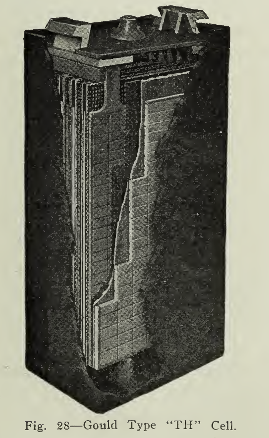
The plates decrease in thickness through seven types so that the proper size, type and thickness of plate is available for each class of vehicle service. The so-called "thick" or "standard" type plate is designated by this Company as type RP, and the medium “Hycap” as MC. The TH and THS are the thin plate types. Types NR, NM and NH are the corresponding designations for the thick, medium and thin plates in the narrower style of plate. These types include the medium, thin and high capacity thin plates as shown in the accompanying tables.
In the higher capacity types this Company claims to have succeeded in developing combinations which will give increased total mileage life in direct proportion to the increased mileage per discharge; that is, the total number of discharges is the same for the higher capacity type as for the "standard" or "thick” plate, so that increased mileage per discharge results in increased total mileage life. They claim this is particularly true in their type MC.
The detail construction of batteries and their plate combinations are designed to meet the generally accepted standards of vehicle manufacturers as regards number of plates per jar, size of jar, medium or high bridges, different forms of connections between cells, battery accessories, etc., as shown in Figure 28.
Philadelphia Storage Battery Company
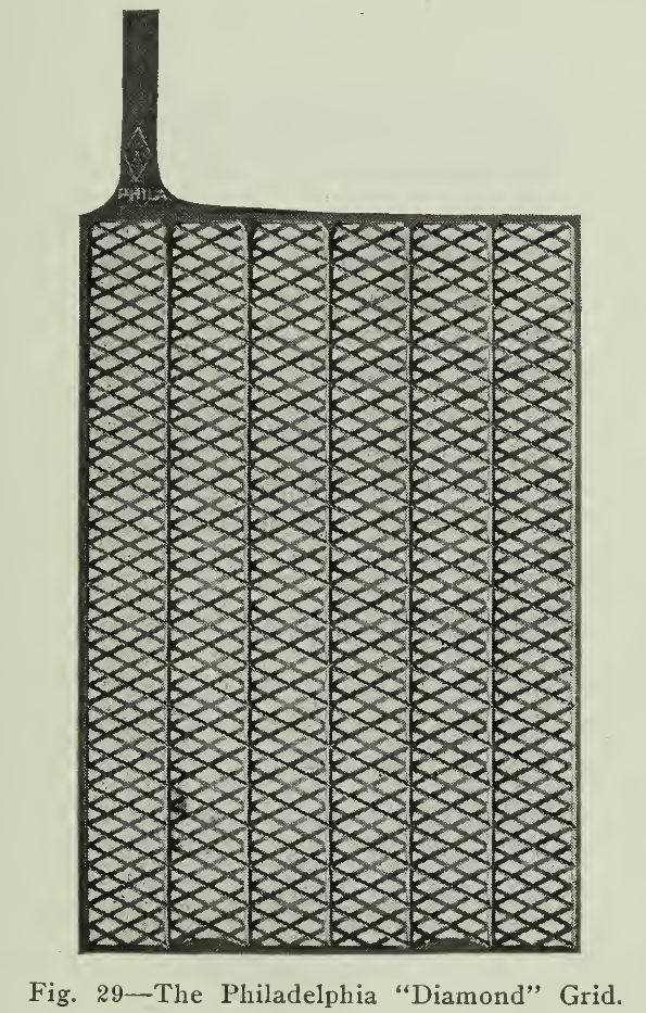
This Company has developed a very successful type of plate which receives its name from the construction of the frame, the "Diamond Grid." Figure 29 shows a skeleton obtained by placing two sheets of diagonal lead net opposite each other and allowing space between for the active material so that when the compound is finally pressed into place the plate is given a smooth surface with the active material confined within the staggered meshes. These staggered diagonal members are designed to give strength for resisting a buckling or warping action and is a firm support for the active material so that hard service may be endured through a considerable life.
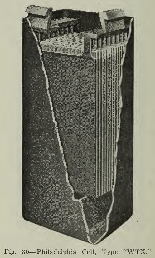
The Philadelphia plates are made in the thick, medium, thin and extra thin types with sizes of each type varying slightly according to the service application in order that the minimum weight with the maximum life and capacity may be secured. The most prominent of these is known as the "WTX" or "Diamond X" (Fig. 30), an extra high capacity thin plate which represents an increase of approximately 54.5% in capacity over the Standard thick plate, type "W" The positive and negative plates are so designed and the space for sediment increased with extra high ribs (2 3/4") that no renewal or cleaning is necessary during the useful life of the battery. This type of plate is recommended by the makers for the majority of vehicle battery equipments because of its light weight and the extent to which the chemical actions penetrate its body.
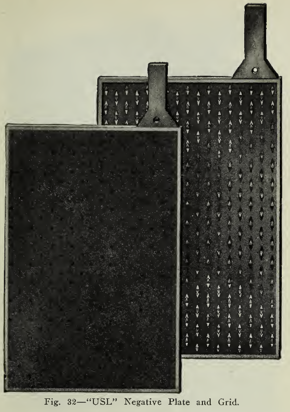
United States Light and Heating Co., N. Y. C., “USL”
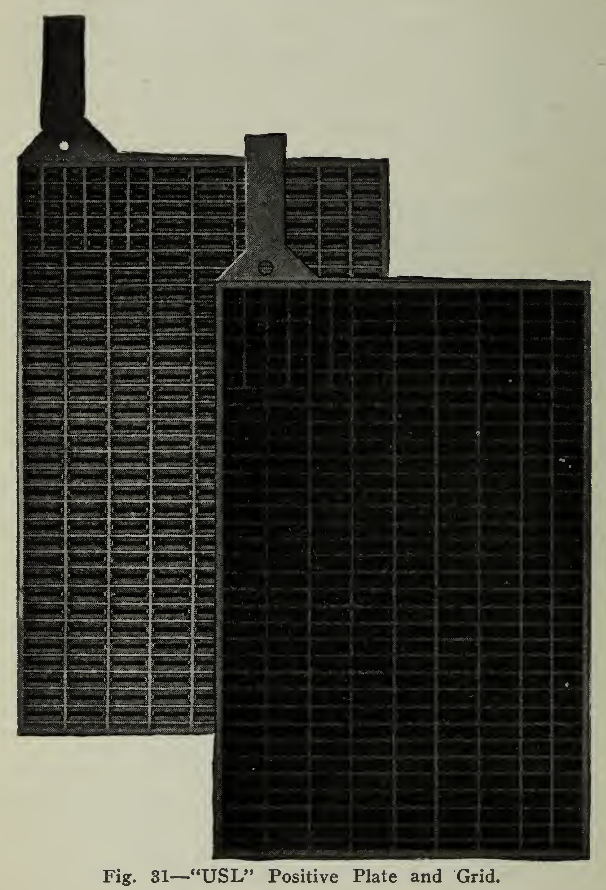
A glance at the illustration in (Fig. 31) will serve to show the method of construction of the staggered bar grid used in the manufacture of this plate. The “CB” negative grid shows a variation from that found in the other types. The metal web is perforated so that triangular prongs are raised from the sheet metal of the grid and serve to firmly hold the active material in place. The retention of a maximum amount of active material considering weight and wear is claimed for this arrangement. The careful methods used in the manufacture of the component parts and finished plates are reflected in the quality of service which results.
The ribs supporting the plates are furnished with soft' rubber tops so that the vibration and jarring from travel over bad roads will be cushioned and reduced, thus eliminating a source of loss of active material.
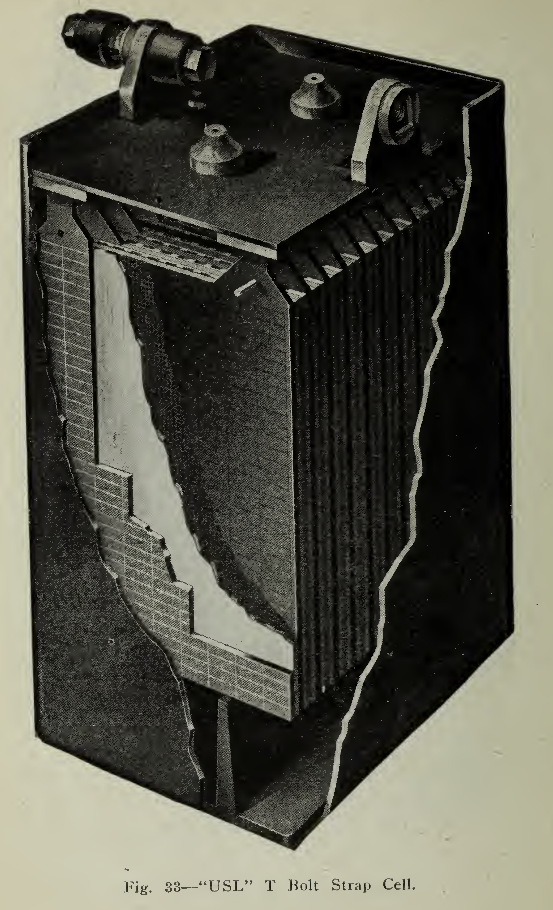
The types of plates include those of the medium and thick design so that the fields of electric vehicle service are covered. The construction of the plates with either "L" or "T" strap or pillar post connectors admits of flexibility in the methods of assembly for either side or end assembling of cells. The bolt connector shown in (Fig. 33) makes a still more flexible arrangement where the latter may be necessary.
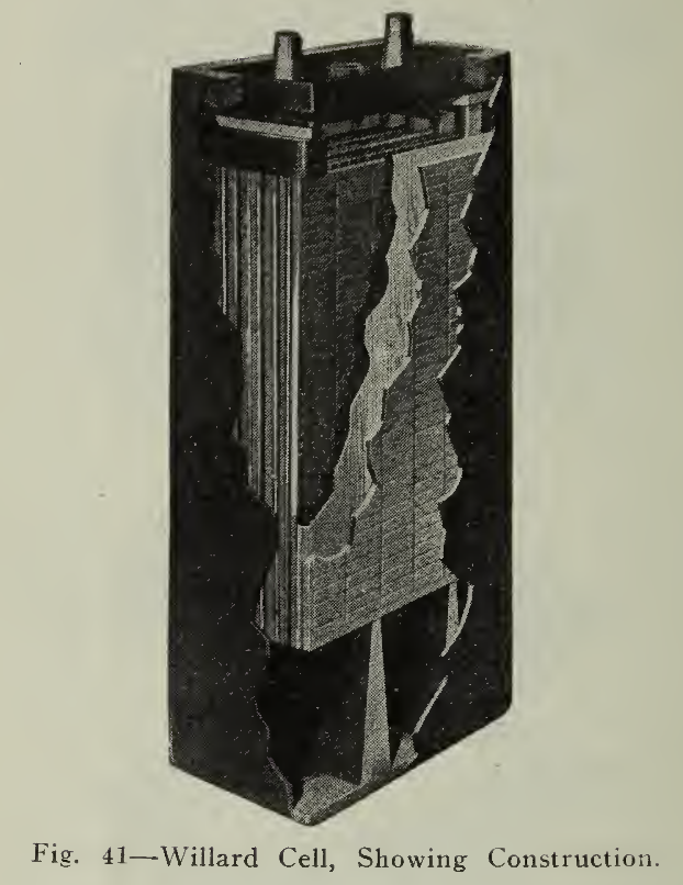
Willard Storage Battery Company, Cleveland, Ohio, “LBA”
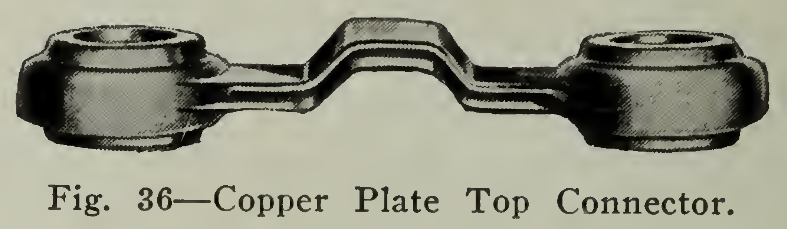
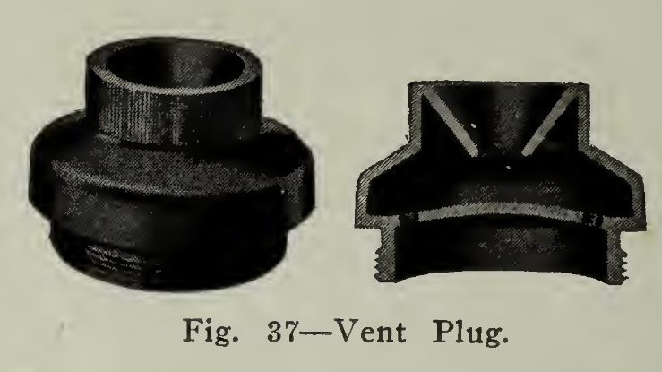
In the manufacture of the "LBA" type of battery a great deal of attention has been paid to the perfecting of the numerous details connected with the manipulation of the battery after it is put into the user’s hands. These include jars with heavy walls to insure against breakage. These jars (Fig. 34) are furnished in two depths so that should a deep space be required for the collection of sediment, obviating the necessity of cleaning, the deeper cell may be used. The connectors are made in either the pillar type burned link or the unbreakable connector formed by using lead plated copper as a connecting medium (Figs. 35 & 36). For use where quick connecting or disconnecting may be required, the pillar posts are threaded to accommodate the bolted top connector screw which secures the bolted connector into place. In addition to these features, the plates may be assembled with either the "U" strap or "T" strap connectors. A vent plug is furnished as shown in section in (Fig. 37) for the purpose of allowing the gas to escape without carrying electrolyte spray with it.
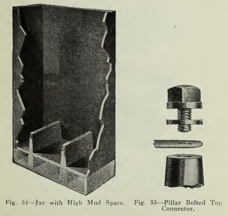
Fig. 35 — Pillar Bolted Top Connector.
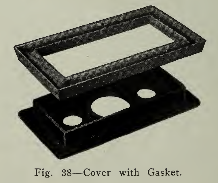
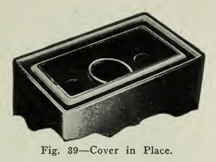
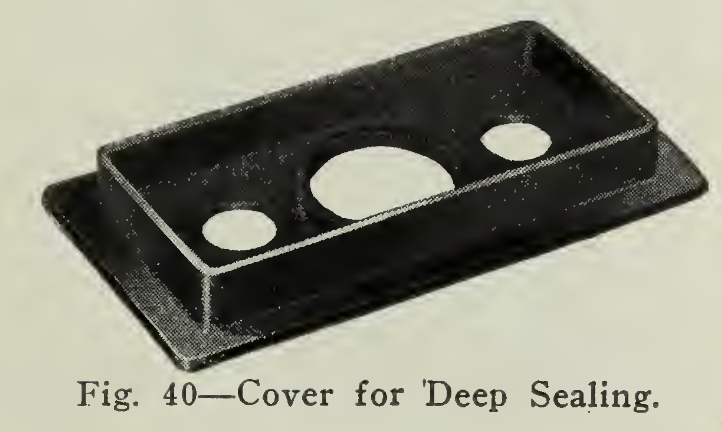
The plates (Fig. 41) are of the staggered bar grid construction with active material pressed firmly into place leaving a flat surface and are made in the heavy, medium and thin types. Lastly, covers (Figs. 38-39) are available for these cells which permit quick sealing by the use of a pure soft rubber gasket. This allows the cover to be inserted over the gasket sealing the jar immediately and just as readily removable. Where this is not necessary the cover is furnished so that deep sealing with compound can be accomplished with little trouble by the extra wall shown in the sketch (Fig. 40).