Last Update: March 10, 2018

In the explanations of operation and instructions for the care of practically each item of the electrical apparatus concerned with the electric vehicle, reference has been made to the electrical quantities, current, potential, resistance and power. These are measured respectively in terms of the units, amperes, volts, ohms and watts. The unit of electromotive force (the volt) will cause unit current (one ampere) to flow in a circuit of unit resistance (one ohm). This expression is a simple but fundamental equation of electrical phenomena and is called Ohm’s Law. From it are derived, by the application of proper mathematics, all of the whys and wherefores of modern electrical engineering. For the purposes of this book, however, it is unnecessary to complicate matters with these technicalities. The simple relation given above is sufficient for an understanding of the usual manipulations incident to electric vehicle operation.
The flow or passage of current in a circuit produces a definite amount of power, which is measured in watts. The watt is the product of one volt and one ampere. The kilowatt is 1,000 watts. Thus the amount of energy used in one hour, when the power exerted in one kilowatt, is one kilo-watt-hour.
These quantities defined in terms of the units are very readily measured by means of the electrical measuring instruments, ammeter (ampere-meter), voltmeter, ampere-hour meter, and watt-hour meter.
Voltmeter. The voltmeter indicates the difference of potential, or voltage, of any number of cells of the storage battery or of the supply circuit from the power station. The magnitude of the voltage to be measured determines the range of the instrument. The scale of the instrument depends upon the voltages to be measured normally and the highest which may be measured. The scales usually used are 0-3, 0-15, o-110, 0-150, 0-250, and 0-300 volts. The scale shows the maximum voltage for which the instrument is to be used, as higher voltages would send too much current through the fine wire of its coils and burn them out. The meter measuring up to 3 volts is used for indicating the voltage of individual cells of the battery and should not be used on more than one cell. A meter of 150-volt range is suitable to measure any voltage up to 150 volts, such as the complete battery voltage or the voltage of a charging circuit of no or 125 volts. If the wiring be of the three-wire system having 230 or 250 volts across the outside wires, then it is evident that the meter should be used only between the neutral and the outside wires, and not placed across the 250-volt potential. For the measurement of this voltage, an instrument having a 300-volt scale should be used.
The scale is a part of the instrument, is calibrated and is correct for its own instrument only. The question might be asked if placing a o-150-volt scale on a 0-3-volt meter would permit the measuring of potentials up to 150 volts. From what has been said above it should be clear that such cannot be done as the wiring of the instrument is sufficient only for 3 volts, as indicated by the scale.
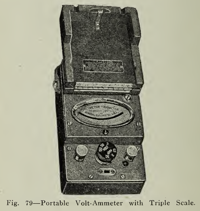
Figure, 79 illustrates a voltmeter which adequately fulfills the requirements of a small portable combination instrument for general testing of apparatus operated with batteries, or testing of any low voltage direct current circuits. The instrument contains in a single case, an ammeter of three ranges and a voltmeter of three ranges. These instruments are arranged to show polarity, have no hysteresis error and are of low internal losses, employing permanent magnets so as to correctly measure the average value of a pulsating direct current — this being the value generally required for storage battery work, especially where charging is effected from a mercury arc rectifier. The instrument may be used to measure either a 3, 30 or 150- volt capacity, and in amperes .3 to 30. The instrument is easily connected, having only two binding posts. By turning a rotary switch, any one of the various capacities is set.
The leads of a voltmeter are thin flexible copper insulated wires attached to the positive and negative binding posts of the meter. The free ends are then applied to the source whose potential is to be measured. Both leads must first be secured to the meter binding posts before the free ends are used in order to avoid damage from accidental short circuit. The same positive meter terminal is conventionally used for each of the scales when the instrument has more than one. Care should be taken, when the voltage to be measured is not approximately known, to use the high voltage scale to determine the reading roughly so that danger of burning out the low reading coil may be avoided.
The lead from the positive binding post, which is marked (+), should be applied to the positive wire or pole of the battery, and the negative lead upon the negative pole, respectively. Where the voltmeter is used as a means of determining which is the positive wire or tracing out connections, then the positive lead should be held fast to one pole and the end of the other lead tapped on the supposed negative pole. The pointer should be carefully watched when the lead is tapped. If the pointer reads in the right direction, that is, gives a reading on the scale of the instrument, then the assumption of positive and negative was correct. Should the pointer indicate in the wrong direction, however, then the position of the free ends of the leads should be reversed immediately, as a violent throw of the needle in the wrong direction would be very likely to bend it.
The remarks in the preceding paragraphs are general, applying to portable as well as switchboard or dashboard types of meters. Switchboard meters, of course, when once placed in position require no change of connections as they are made on the back of the board so that, when the switches are closed, the voltmeter will indicate. On large switchboards consisting of a number of circuits, it is usual to use one voltmeter and one ammeter for each panel of six circuits, a selective dial allowing the voltage of each circuit to be read.
In order to secure accuracy in electric measuring instruments, it is necessary to have them extremely well balanced. This is accomplished by making the moving system as light as possible and pivoting it upon polished jewels. The instrument is thus as delicate as a watch and so should not be handled roughly. As to making adjustments, it may be said that unless such are explained and recommended by the manufacturers they should not be attempted. It is preferable in the majority of cases to place the instrument in the hands of a competent instrument man or return it to the manufacturer for a small repair rather than to meddle with it and then send it for complete overhauling, as would probably then be necessary.
The low reading voltmeter having a 3-volt range IS made in many convenient forms for use in going over individual cells, on charge and discharge or for cadmium readings. Care should be exercised in the use of such a meter as its usefulness depends upon its accuracy, Fig. 80.

The voltmeters placed upon the dash, or in any other convenient location in the vehicle, are usually combined in one case and on the same base with the ammeter, so that both may be easily and simultaneously noted, Fig. 81. They are made as rugged as possible so as to withstand the effects of travel over rough pavements. The leads are placed so as to give the voltage applied to the motor, whether the battery is in series or in parallel, during the discharge. On charge the cells are practically always charged in series so that the voltmeter then gives the voltage applied across the battery in charging.

As explained under "Storage Batteries," there is a maximum voltage reached on charge and a safe minimum voltage on discharge with normal current flow. These amounts may be, and often are, indicated on the scale of the meter in red lines by the vehicle manufacturers so that they may be readily observed in charging or during operation.
Ammeter. The instrument used to measure the electric current in amperes is the ammeter. It is very similar to the voltmeter in construction, but is placed in series with the circuit instead of across it, as shown in Fig. 82. What has been said of the scale ranges of voltmeters is also true of ammeter scales, and care should be taken to see that currents in excess of the scale range are permitted only for very short periods, as damage to the meter would otherwise be likely to result. Ammeters used in storage battery work generally have a zero centre scale, as shown in Fig. 83, so that no change of connections need be made when reversing from charge to discharge of the battery. It would otherwise be necessary to do so, as the current flows in opposite directions in charge and discharge.

The ammeter measures the current flowing through a special resistance, known as a shunt. Fig. 84, which may be located within the ammeter case or external and separable from it. Care should be taken to use the meter only with the shunt furnished with it, unless specified otherwise by the manufacturer, as the meter would not give correct readings and might be damaged.
The combined instrument, voltmeter and ammeter, Fig. 83, when assembled in one case for vehicle service, is generally spoken of as a volt-ammeter, and has met great favor in giving the information required in the operation of storage battery vehicles.

The Ampere-Hour Meter. The voltmeter and ammeter are indicating instruments which give the instantaneous values of the voltage and current of the circuit. In practical storage battery operation, however, it is very convenient to have more information than the instantaneous value of current or voltage because, what the operator of an electric vehicle is most interested in, is the mileage capacity of his battery. When starting out with the battery fully charged it is known approximately how many miles the vehicle can be run upon a charge, but, if the operation is discontinued and the car allowed to stand or a routing selected which differs from that previously gone over, then the latter part of the discharge will not be definitely determined unless the ampere-hour meter is employed, which gives a definite indication of the remaining value of the charge.

Readings of voltage at a definite current flow from the battery will give a very close idea of the state of charge in the battery, but, to the inexperienced or when the instruments are not in good condition, the results are not always satisfactory. Readings of specific gravity are the most reliable and at all times give an absolutely correct determination of the state of charge in the battery. Owing to the method of taking these readings, it is evident that such indications are not practical for ordinary vehicle operation, and that some sort of meter, which will record the current which has been put into and taken out of the battery, is needed. Such a meter is known as the ampere-hour meter, Fig. 85, and is designed to measure the current put in or taken out of the battery. It is also designed to compensate in its record of the state of charge or discharge of the battery for any loss which may occur by internal discharge of the battery within itself, which usually takes place when the battery remains unused for any considerable length of time.

The ampere-hour meter is of the Faraday motor type, which depends in principle of operation upon the action of a magnet upon a copper disc armature free to rotate while carrying current The sectional illustration (Fig. 86) shows the construction of the meter with the permanent magnet omitted so as not to complicate the drawing. The armature disc in this instance is of copper, rotating, and submerged in a chamber of mercury. The current is conducted to and from the disc by contacts imbedded in suitable insulating compound in the walls of the chamber. The mercury carries the current from the contacts to the armature, and also produces an upward thrust on the axis of the armature so that there is no pressure on the lower support or bearing, and only a slight pressure on the upper support which is practically the only bearing. With this construction the manufacturers claim a high degree of accuracy combined with freedom from accident due to constant vibration and jarring such as exists in vehicle operation, all vibration being absorbed in the mercury.

The upper part of this shaft carries a worm that engages with a geared wheel which, through a proper gear train, operates a movable hand or pointer rotating in front of the face or dial of the meter. The current, or a portion of it from the meter shunt, passes through the armature of the meter and is reacted upon by the powerful, permanent, driving magnet, so that in combination with the gear train, mentioned above, the large pointer will rotate, the speed and amount of rotation depending upon the current flowing and the time. The voltage is not in any way recorded since we are interested particularly in ampere-hours.
Intelligent use of the ampere-hour meter is a safeguard against too frequent charging of the battery, overcharging and heating. It is well recognized that the most reliable method of determining the state of charge in a battery is comparison of the change in specific gravity by means of the hydrometer and the use of an ammeter. This method, however, can only be taken advantage of when there is direct access to the battery, or it is removed from the vehicle; and consequently, the ampere-hour meter is the most convenient means of continuously keeping the state of battery charge under observation.
In the case of the lead battery, the specific gravity is a definite indication of state of charge, but in Edison batteries it tells very little so that the meter is found to be even more useful with the alkaline battery than with the lead battery.
The meter equipped with a single shunt records the true ampere-hours charged into the battery and those drawn from the battery. It does not take into account, however, the fact that it is necessary to put more ampere-hours into the battery than can be removed from it in any succeeding discharge. In order to compensate automatically for this inefficiency, an arrangement known as a "differential shunt" is incorporated in the earlier types of this meter, but this device has been superseded by a "Resistor Element" in all later instruments; both allowing a percentage overcharge to be given. There is a range of adjustment for 10 to 25% variation. Lead batteries are generally set from lo to 15 per cent, slow and Edison batteries from 15 to 25 per cent. The amount of overcharge thus given is determined by the class or condition of service in which the vehicle is to operate. If the vehicle is to be only partly discharged each day or used in a section of good and level roads, then it does not need as much overcharge as when it covers a severe route.

It will be noted that there are two methods which may be employed in showing the recording on the meter dial. One is to have the hand move clockwise on discharge and counter clockwise, or back to the zero point or top of the dial, on charge, while the other is to reverse this sequence. The advantage of the former is that the position of the hand at any time during discharge shows exactly how many ampere-hours have been taken from the battery, and, when the pointer reaches the zero mark in charging, then use may be made of a zero contact or "stop charge" feature. The second arrangement mentioned does not allow of this automatic feature, but gives a direct reading of the amount still available in the battery.
The instructions which have been given in Chapter III. on the care and operation of storage batteries are not affected by the use of an ampere-hour meter, and precautions which are given there are not to be abridged with the use of this instrument. The regular overcharge which is prescribed for both lead and Edison batteries should also be given, and may be accomplished readily by resetting the main hand the desired number of ampere hours before beginning the charging.
The resetting device for the main hand, while not necessary for ordinary charging, may be found very useful for the regular overcharge every two or three weeks, or when a new battery is substituted for the one which has been operating in the car, and the position of the hand on the dial is not “in step’’ with the battery, that is, when the pointer does not give the true condition of charge in the battery. By this means it is possible to arrange the pointer so that, when it reaches the zero mark after allowing the required charge, it will operate the zero contact feature and discontinue the charge automatically. The manufacturers have furnished the device with a cap so that tampering by unauthorized persons is avoided, and injury by jamming or stripping of gears in the clockwork while resetting is prevented.
The zero contact or stop charge feature, which has been referred to in preceding paragraphs, consists of a contact at the zero point on the dial operated by the pointer. When the pointer is revolved back to the zero position indicating that the battery is fully charged, then the contact completes a circuit to a circuit-breaker, which causes the latter to open, discontinuing the flow of current through the battery to which the meter is connected. This device depends only upon the ampere-hours and not upon the voltage of the supply circuit or the battery, differing from the method employed in the mercury arc rectifier, where the current is reduced as the effective voltage deceases as the charge progresses. This is a very convenient feature in many instances, among which may be mentioned the small private garages in which a pleasure vehicle may be placed upon charge late in the evening, or after reaching home from the theatre, and the charge automatically discontinued during the night or early morning, according to the amount required, without necessitating further attention from the owner.
The dial of the meter is graduated in ampere-hours and the unit number of ampere-hours, per revolution of the hand, should be somewhat more than the greatest discharge capacity of the battery, so that, if it be required to give an overcharge. making use of the resetting of the main hand, the complete charge in ampere-hours may be indicated upon the dial. Sometimes a second hand is added, turned by means of a knurled head at the centre of the glass in front of the dial. This hand is not connected with the main hand or mechanism of the meter in any way and is used only by the operator in being set at an arbitrary reading of the dial for reference such as the maximum safe discharge capacity. Thus as the battery increases in capacity during life, the position may be changed using a gradually increased reading as the safe maximum discharge.

As explained above, the large hand operates through suitable gearing, and, as it rotates the meter speed is proportional to the ampere-hours and will indicate the, ampere-hours input plus the necessary overcharge, or the true ampere-hour output.
This large pointer gives the condition of charge for one cycle of charge or discharge, as it operates in one direction for charge and in the reverse direction for discharge.
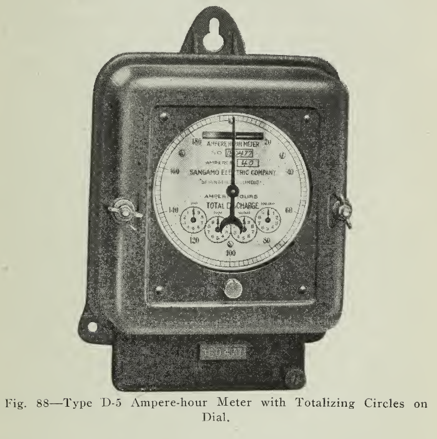
In addition to this pointer a recording train is sometimes included, Fig. 88, this being so connected to the pointer through suitable gearing that it will record the total ampere-hours of charge or discharge during several cycles, or for any considerable period.
For special cases it is possible to furnish a dial, termed by the manufacturers the "Duplex Train," Fig. 89, arranged to record the total of both charge and discharge. In using this arrangement, however, it is not possible to use the large pointer to indicate the condition of the battery for each individual charge and discharge. For any given voltage the readings of charge may be calibrated upon the dial in kilowatt hours instead of ampere-hours input. In connection with an odometer or other mileage recording device, complete and detailed results may be thus obtained by means of such a meter.
The ampere-hour meters are constructed in two general types known as the self-contained meter and the distant dial meter. The first named is manufactured in three styles, called the Auto type, the Service type and Extension Back type. Electrically all three of these are identical, the differences being only in the arrangement of the base casting upon which they are mounted and the special way in which the leads are brought into the meter.

The Auto type is supported upon an aluminum base and is intended for location in passenger vehicles in position for easy reading.
The Service type is slightly larger than the Auto type and is mounted upon a solid cast iron base with lugs for external line connections.
The Extension Back type, is contained in a pair of aluminum castings so arranged that the meter is supported by lugs at the front, allowing the dial, with friction tight bezel ring and cap only, to protrude through the heel or dashboard.

In some cases it is not convenient to place the meter, in the forms described above, in the most suitable location in the car body on account of the space it would occupy and the heavy wires leading to it. To meet this demand the manufacturers supply a meter of the Distant Dial type. This arrangement allows the meter proper to be placed out of the way, as beneath the seat or supported on the chassis. The dial mechanism may then be located within the body of the vehicle at the most convenient spot. This dial mechanism is furnished in the flush or projecting- type as shown, 90.
OPERATION OF CONTACT MECHANISM AND DISTANT DIAL.
Instead of the recording mechanism as described for the standard meter, in which the shaft drives a hand, a contact train, Fig. 91, is provided which closes a contact to the distant dial mechanism at equal intervals of ampere-hours measured by the meter. The dial mechanism consists of two electro-magnets facing each other, and provided with a lever free to rock between them. The energizing of one of these attracts the lever on charge, the motion thus imparted advancing the hand one division on the dial toward the zero point. During discharge a similar series of impulses through the other electro-magnet change the position of the dial hand in the opposite direction from that travelled during charge. Should the leads connecting the contact-making mechanism with the dial mechanism be broken, the meter proper would not be affected, as the rotation will continue, the driving wheel of the contact train simply escaping past the bar operating the contact in either direction.

The zero contact feature is provided in the distant dial type as well as the standard type of meter, so that an auxiliary circuit breaker may be operated, opening the charging circuit.
Leads and cables connecting the meter and dial to the charge and discharge circuits are furnished in distinct colors so that, with the diagrams, the proper connections may be readily effected with small opportunity of error.
Ammeter and Distant Dial. Since the introduction of the distant dial type of ampere-hour meter, the suggestion was made that the scales of all the electrical instruments carried on the vehicle, such as voltmeter, ammeter and ampere-hour meter, be combined in one case. This may be readily accomplished. A recent design, illustrated in Fig 81, shows the distant dial and ammeter scales.
Compensated Meter for Lead Batteries. As explained in Chapter III, it is characteristic of lead batteries that the discharge capacity in ampere-hours varies with the discharge rate, the higher the latter the lower the capacity. For instance if the normal rate of a particular battery is 27 amperes for 5 hours the capacity being 135 ampere-hours, then at three times the normal rate experiment shows the capacity to be only 90 ampere-hours. In such an instance 45 ampere-hours would be lost, ostensibly, but such is not the case as in practice such an extremely high rate is not maintained for but very short periods, except under the most unusual circumstances. In going through sandy or heavy roads or climbing long hills the current draw will be considerably increased and the capacity thus reduced. However, this is partly offset in practice by the short periods for which these overloads are borne and the ability of the battery to recuperate.
In the compensating type meters designed to provide for abnormal rates of discharge, the speed of the meter is automatically increased, and so compensates for the condition explained above.
SMALL AMPERE HOUR METERS
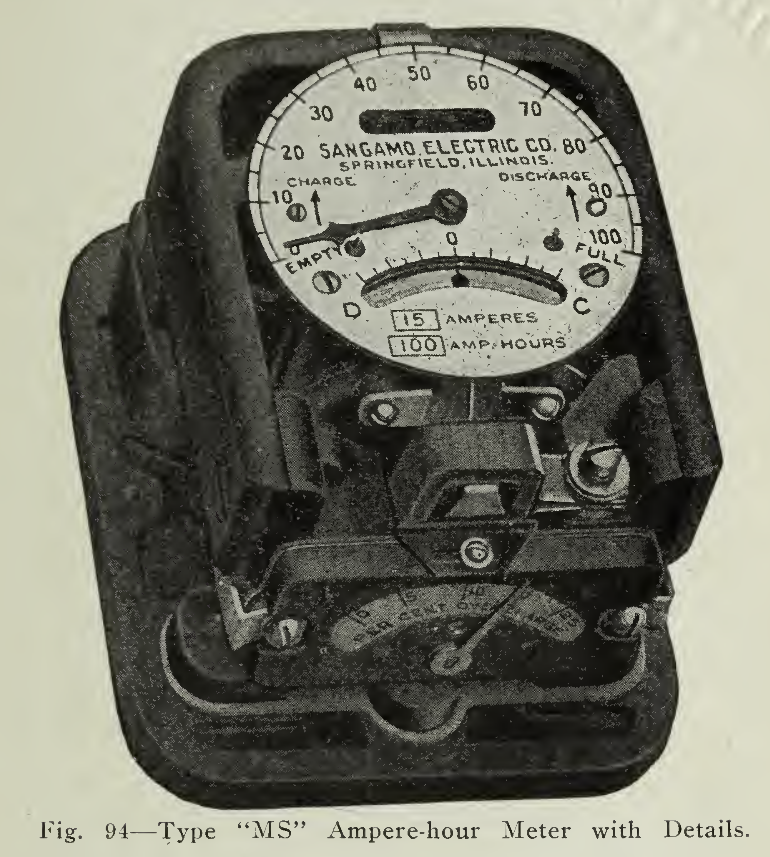
The "MS" meter is similar in all respects to the Sangamo standard D-5 ampere-hour meters, except that it is much smaller in size. The general appearance of the meter is shown on page 208, figure 93. It is so small that it can be conveniently held in the hand and can be installed on the dash-board of an electric vehicle or gasoline car, as it occupies no more space than a clock or speedometer. It weighs less than five pounds.
The Type "MS" meter is made with two styles of dial — the circular ampere-hour dial and a combination ampere-hour and ampere dial. The, former is simply a regular Sangamo ampere-hour meter circular dial, shown on page 208, figure, 93, while the latter is a circular dial having an ampere-hour scale that extends a little less than two-thirds around the upper part and the circular scale near the bottom, shown on page 209, figure 94. The internal construction of these two meters is exactly the same except that the latter is equipped with a current indicator.

The "MS" meters have been especially designed to meet the requirements of small storage battery installations such as are used in isolated lighting plants or in connection with the ignition and lighting systems of gasoline automobiles, motor boats, etc.; also for use on electric vehicles. They are not injured by the severe shocks and jars incident to operation in automobiles.
The plain circular dial type meter is intended for electric vehicles where separate ammeters are already available for measuring the current. This type, meter is regularly furnished with a red hand stamped with the word "Empty" and this can be set at any desired point as a guide to the user. It is also furnished with an insulated contact at zero, or full charge point, which is closed by a platinum tip on the indicating hand, thus operating a circuit breaker or signal device, when the battery is fully charged. Contact points may be located at any position on the dial to operate signals or relays at certain points in the discharge of the battery.

Like larger meters, it is arranged for automatic overcharging of the battery, and the desired percentage of over-charge can be set by means of a lever which moves over a scale at the base of the meter, as shown on page 209. Where desired, the regular type ampere-hour meter without the current indicator may be equipped with the compensating device which makes allowances for loss of capacity for high discharge rates.
Installation and Connections. The ampere-hour meters, as furnished by the manufacturers are complete, ready for installation, which is a comparatively simple matter requiring only the placing of the instrument in a convenient location where it may be easily visible, accessible for adjustment and resetting, and convenient for the wiring. When placed upon a dashboard which is inclined, the meter should be blocked so that the disc will rotate in a horizontal plane. If possible it is preferable to place the meter beneath the seat in order that it may be protected from the weather and the feet of the driver.

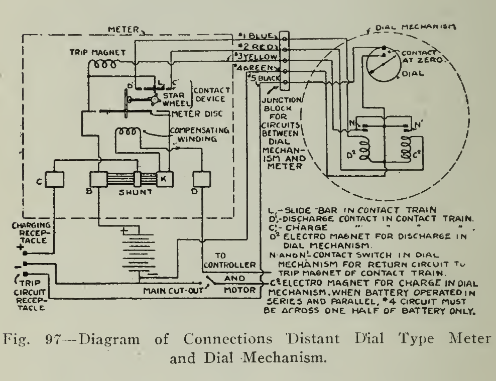
The wiring scheme is shown in Figs. 96 and 97 which illustrates the method of connecting the charging plug, controller, battery and circuit breaker, Fig. 95, with the meter.
This diagram of connections, with modifications depending upon special wiring of the different makes of cars, can be generally applied. Care must be used in making the connection when the battery is divided for parallel operation during part of the time and operating in series on the higher speeds. When the cells are connected in parallel during discharge then the current from one branch only should pass through the meter and not the total current to the motor, because an erroneous reading would be thus obtained. For charging, of course the battery is connected in series, and all of the current passes through the meter in the same manner as when the cells are all in series on discharge.
Inspection of all parts of the vehicle is necessary and the ampere-hour meter should not be neglected as it is very necessary to maintain all of the bolts, nuts, screws and contacts firm and secure so that loose contacts may not develop, causing heating or even burning of terminals. When new it would be well to go over the nuts and screws every two or three weeks, tightening the connections if necessary and thereafter approximately every month or two. When doing this the battery contacts, in fact all the electrical leads or wires, should be inspected to see that good contact is made and that the joint is secure.
Should damage of more than very slight nature be imposed upon the meter, it is preferable to remove it from the vehicle and return it to the manufacturer or competent instrument maker for repairs, rather than to submit it to the tampering of an inexperienced repair man.
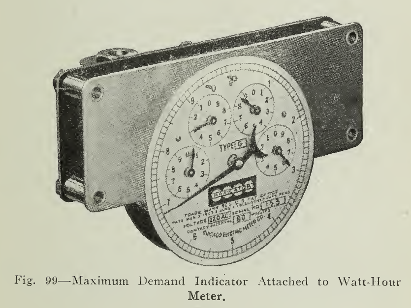
Maximum Demand Indicator. In some communities the cost of electricity is based upon two items, the first being a charge for the readiness to serve, taking into account the highest point of demand during a predetermined period; the second takes notice only of the total amount consumed in the time indicated. The monthly consumption is measured by a watt-hour meter, while the maximum demand is derived by taking either a percentage of the total connected load of the installation, by the use of a Demand Indicator, or, in the case of very large consumers, by measurement of the maximum load.

There are a variety of instruments used for the large installations but the recording of the maximum values of current for the smaller consumers is done by the indicators illustrated in Fig. 98, 99 and 100. In the Demand Indicator shown in Fig. 98, the flow of current in the circuit for a period of five minutes or more will cause the liquid in the index tube of this instrument to rise to a point opposite the scale of current. The liquid will remain at that point until it either is raised by the recording of a higher value of current or is reset.
Resetting is accomplished by tilting, allowing the liquid to return to the main liquid chambers. Frequently there are two scales, one of current in amperes and the other calibrated in kilowatt hours for the potential of the circuit, as 115 or 230 volts. In this manner the electricity meter and the Demand Indicator may be quickly read and reset by the authorized meter reader and readily checked by the consumer.
The instrument shown in Fig. loo is designed for use with a watt-hour meter, and prints on a tape the watt-hour consumption during the small time intervals also printed in adjacent position on the tape. This indicator may be used for either direct current or alternating current circuits.

The device illustrated in Fig. 99 takes the, place of the watt-hour meter register, and also includes a large hand which indicates the maximum watt-hour consumption during half hour intervals. The mechanism is arranged so' that, if the rate of consumption be less during succeeding intervals, the reading of the hand will not be altered, but if the rate at which the energy passing through the meter increases, then the hand will be moved to a position of greater demand. This device is applicable only to alternating current circuits, but modifications are provided so that the same principle may be used with direct current installations.
Watt-Hour Meter. The watt-hour meter records the electric power consumption, taking account of the current, the length of time for which it is used and the pressure or voltage at which it is supplied. The meter used for the purpose of measuring the electricity supplied in charging a storage battery does not differ from those installed for recording the consumption of light or power in factories or residences.
The external form of these meters is no doubt familiar to all. The internal construction, while interesting, cannot be explained within the scope of this book, but the readings of the dials deserve consideration at this point so that the methods of arriving at the cost of current may be understood.
The dials shown in Figs. 101 and 102 illustrate die meter readings. After noting the direction in which the pointers are moving, read the number on the dial that has been passed by the pointer, that is, the lower number. If there is doubt as to whether the pointer has passed the number or not, inspection of the next lower dial will determine. If the hand on it has started on a new revolution, then the pointer on the first dial has passed the doubtful number. The readings are recorded in kilowatt-hours, and the difference between two readings gives the number of kilowatt-hours consumed in the period intervening.
The cost of current for battery charging varies considerably in different parts of the country, depending upon the number of vehicles charged regularly, whether they are all charged at one time or consecutively in sets, and also naturally upon the cost of producing and distributing electrical energy in the particular district. Owing to the fact that the vehicles are charged during the night when the residence and industrial loads are light, special rates are usually extended in favor of this class of customers. Fortunately, this is profitable both to the central stations and the vehicles owners, since it provides off-peak load for the former and lower rates for the latter. The peak load refers to the periods of greatest demand on the power stations.


Remarks on the installation and maintenance of watt-hour meters are unnecessary in this connection since they are installed and inspected periodically by the central station companies, excepting in such public garage installations as desire more detailed records for their own information. In such cases, arrangements can be made for competent supervision.

Fig. 104 — Centrifugal Speedometer.
Mileage and Speed Indicators. In the operation of motor vehicles it is usually not only convenient and advisable, but very often necessary, to know the speed and distance characteristics of the vehicle. In the measurement of distance and speed, including the variation of the latter, many devices are used and they may be divided into two classes, namely, those which give the instantaneous readings of speed and those which record its variations over a predetermined period.
Fundamental quantities involved are time and distance. Time is measured by a clockwork of the familiar type, while distance alone is measured by a type of odometer. The odometer is usually geared directly to one of the forward wheels of the vehicle although, when combined with a speedometer, the device is generally placed within the car or upon the dashboard for easy reading and actuated by a flexible shaft from the wheel. The simplest type of odometer is that which is placed upon the wheel itself, Fig. 103, and consists of several small toothed wheels and a recording train showing the actual mileage for the size of wheel to which it is geared.

The speedometers are of four general classes, the centrifugal, hydraulic, magnetic and electric.
The centrifugal speedometers are among the most widely used and depend upon the action of a revolving weight against a spring, Fig. 104. The greater the speed of rotation of the weight, the more intense is its effect upon the stationary spring, so that a pointer attached to the latter will be revolved over a graduated scale or dial face. Any changes in speed are quickly taken up by the sensitive instrument and indicated by the pointer.
The hydraulic speedometer consists in the use of a liquid, such as oil, in a tube or chamber containing a small paddle wheel. The flexible shaft from the road wheel is geared to this small paddle wheel, which sets the oil in motion, propelling it to a height in the tube proportional to the speed of the paddle, that is, to the speed of the car. The illustration. Fig. 105, shows this instrument ready for installation.
The magnetic speedometers. Fig. 106, are also very extensively used. They depend upon the magnetic attraction between a revolved magnetic core and an attracted aluminum cup carrying the indicated speed digits. The attraction between these two, balanced against a spring of special temper, makes the indication in the window of the instrument, at which the numbers appear, dependent upon the speed of the flexible shaft or, in other words, upon the speed of the car.
When it is required to record mileage as well as to indicate the speed, a small recording train is also actuated by the flexible shaft within the speedometer case.

The electric speedometer or tachometer consists of a small electric generator driven from the wheel of the vehicle and connected by two thin wires or leads to the indicating instrument, which may be located in a convenient part of the car. The indicating instrument is in reality a voltmeter calibrated, that is, its scale is graduated in miles per hour instead of volts. Ordinarily this type of instrument is very little used in vehicle application and does not include a mileage recording device.
Frequently it is very convenient and advisable to know the exact slope or grade of a hill, and for that reason an instrument, known as a gradometer, may be attached to the car or secured as a unit with some makes of speedometers. This gradometer is simply a liquid in a tube with a scale marked in per cent, grade. It is very similar to. the carpenter’s level in which the bubble under the centre mark shows that the work is true.
The devices mentioned in the preceding paragraphs are very extensively used, both on commercial and passenger vehicles, and it is safe to say that there is a negligible per cent, of the total number of vehicles in use which are not equipped with one or more of these instruments.
Meters which give a permanent record of the traveling time, standing time, etc., of vehicles are important especially in commercial service where it is highly desirable that the most effective work possible shall be obtained from the trucking equipment. These instruments are, as yet, not so widely used as their importance would warrant, but owners of commercial vehicles are increasingly recognizing the value of using travel recording instruments upon their trucks. From records made by such instruments, it is possible for the delivery superintendent or supervisor of the vehicle service to inspect the movements of all the trucks throughout each day, and to plan or devise methods for increasing their efficiency, either by changing the loading, the drivers or rearranging the routing. In many cases, very complete records of this nature would leave nothing to be desired toward increased efficiency, but such records could only be assured, without the use of travel recording instruments, by the continuous services of trained -and skillful observers to ascertain the details.
Aside from the value of the travel record as an index of a truck's performance, the moral effect exerted upon the driver, through the automatic recording of all delays of his truck, is very considerable, and cannot fail but impel him to use his time to the best advantage.
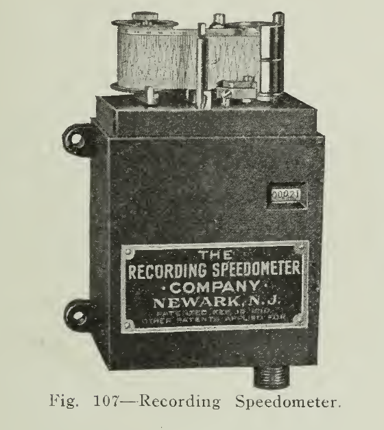
Several recording instruments of this class are operated through flexible shafts. One of these is shown in Fig. 107. The driving gear on this type is attached to one of the wheels of the truck. The instruments proper are so protected in their cases that practically no attention is necessary. The exposed wearing parts should be inspected frequently, and kept free from mud, and oiled or greased moderately.
The recorder shown in Fig. 108 is unique in that it has no outside shaft connecting it to the vehicle wheel. It is a self-contained instrument and is operated on the well known principle of the pendulum, the ever-present oscillations caused by the side thrust of the vehicle when in motion being the basis of a record on the time chart. Ordinary vibration or jar of the vehicle, are not recorded. The makers lay considerable emphasis upon the lack of a flexible shaft connection, pointing out that such devices are easily damaged by any sort of malicious interference, and that they are. more liable to breakage than a self-contained instrument having no outside gear connections of any kind.

A form of recording device which is very widely and popularly known in the large cities is the taximeter, which is a form of travel recorder arranged to show its record in Dollars and Cents as well as in miles. These devices are well known and need no particular comment here.