Last Update: March 10, 2018

Of this class of cells there is but one combination of elements which has met with practical success. The Edison battery has the same general characteristics as the lead battery but no lead is used in its construction and the electrolyte is a solution of caustic potash instead of sulphuric acid.
The peculiarities of construction and the character of the materials used enable the manufacturers to claim a long term of service for the cells.
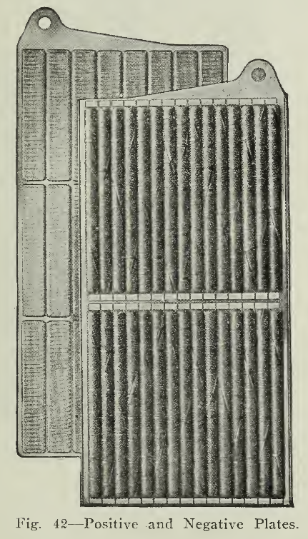
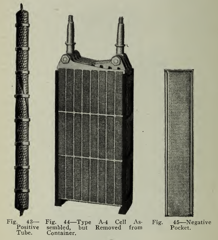
Fig. 44 — Type A-4 Cell Assembled, but Removed from Container.
Fig. 45 — Negative Pocket.
The grids for both positive and negative plates are stampings from sheet steel. These, as well as all other steel parts used in the assembled cell are nickel plated to prevent corrosion. The active material is contained in tubes or pockets, fastened rigidly to the supporting frame or grid and giving electrical conductivity.
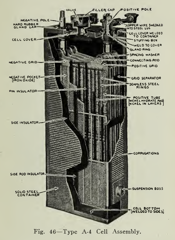
The positive plate (Fig. 42) is built of horizontal rows of fifteen (15) vertical cylindrical steel tubes containing the active material nickel hydrate, interspersed in thin layers with pure nickel flakes. These flakes are used to give good conductivity between the hydrate and the tubes. These tubular containers (Fig. 43) are made of very thin steel ribbon, finely perforated, nickel plated, about 4" long and in diameter. The ribbon is wound in the form of a spiral with the edges double lapped. Nickeled steel rings, or ferrules, at intervals, prevent the tube from expanding. In the Type A Plate there are two horizontal rows of fifteen (15) tubes placed vertically.
The construction of the negative plate (Fig. 42) is very similar to that of the positive, but instead of the nickel active material held in tubes, iron oxide mixed with mercury oxide in this case is tightly tamped into flat pockets (Fig. 45) of finely perforated nickel plated steel ribbon, rectangular in shape and 1/2" wide by 3" long with a thickness of not more than 1/8". These pockets are placed in position on the grid and under heavy pressure, forced into close contact with it, at the same time making the surface of the pockets corrugated, thus supplying a firmer contact between the metal and the active material. The type A plate has twenty-four (24) pockets arranged in three horizontal rows.
The plate frames have a hole located in one upper corner through which a steel stud is passed. Two groups (Fig. 44) respectively of positive and negative plates are formed by arranging the required number of plates with spacing washers and a terminal post at the centre of the stud. The end of the studs are threaded and nuts hold the plates and spacing washers rigid. These two groups f positive and negative) of the cell are placed together so that the positive and negatives alternate, there being one more negative than positive plate. Between the plates hard rubber rods are inserted and serve the purpose of insulating and properly spacing. Pieces of hard rubber in ladder form (Fig. 44) are fitted snugly, by grooving, to the edges of the plates so that a well insulated but firm and rigid unit is obtained.
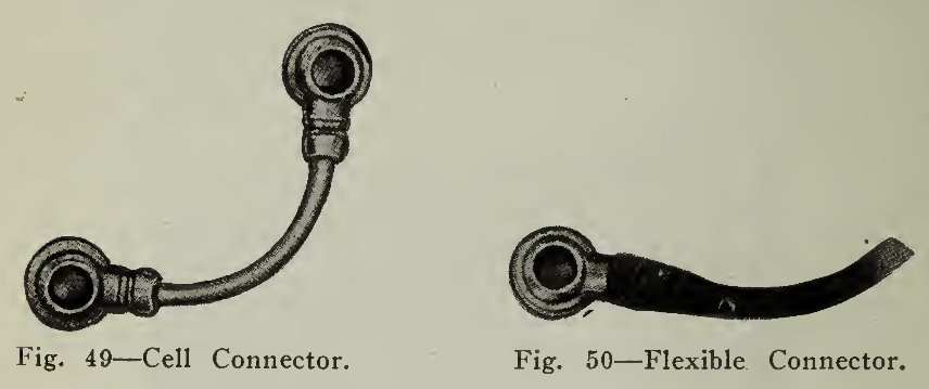
Fig. 50 — Flexible Connector.
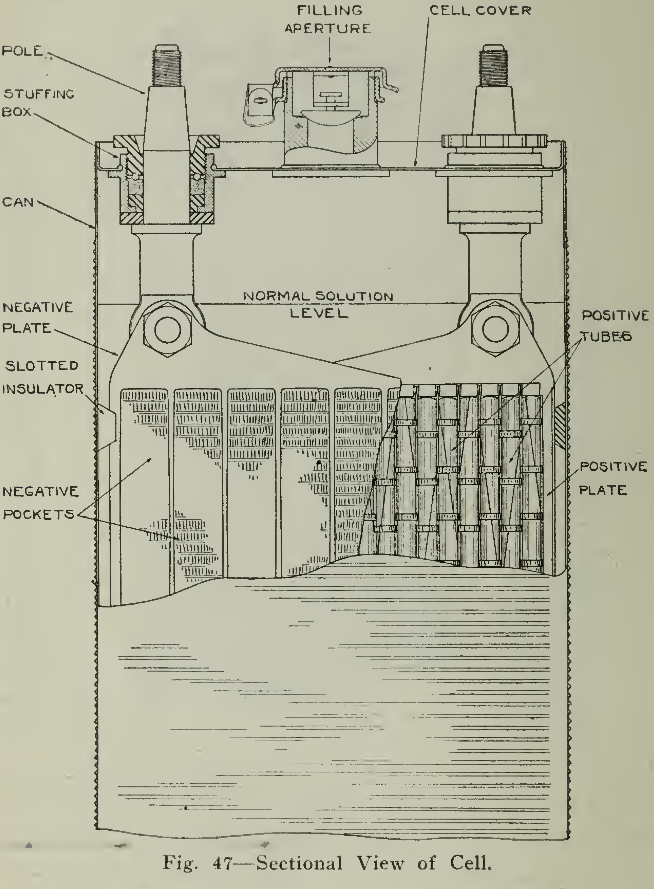
The receptacle used to hold the elements is called, in this case, a can (Fig. 46) as it is made of sheet steel, nickel plated with corrugated sides to furnish strength. The seams on side, top and bottom are welded by the autogenous method with the oxyacetylene flame. The can receives the insulated unit described above, projections at the lower ends of the side insulators (Fig. 44) supporting the plates at the bottom while two thin sheets of hard rubber are inserted between the outside negative plates and the can. The cover (Fig. 47) for this can is provided with two fittings through which the pole pieces pass, being suitably insulated by rubber washers which also prevent passage of gas or liquid. A combination filler and gas vent is placed in the centre of the cover and allows the addition of solution or distilled water to the cell. The hinged cover of this mounting is designed so that the gases liberated during operation may be discharged without allowing entrance of air or impurities as these would cause contaminated electrolyte reducing the efficiency of the cell.
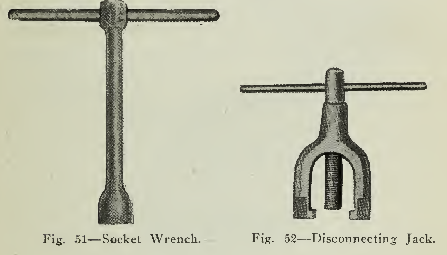
Fig. 52 — Disconnecting Jack.
The welding of this cover into place completes the cell except for the electrolyte, which is a 21% solution of potassium hydrate with a small quantity of lithium hydrate.
The cell is filled with electrolyte until a level of about Yz' above the tops of the plates is reached. The cell is then ready for the forming charges and service conditions. The characteristics of the design and manufacture are such that repairs or replacements, except of a minor character such as external parts and electrolyte, must be made at the factory unless special apparatus is at hand for such work. This would indicate that repairs are seldom required.
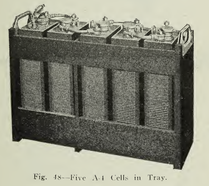
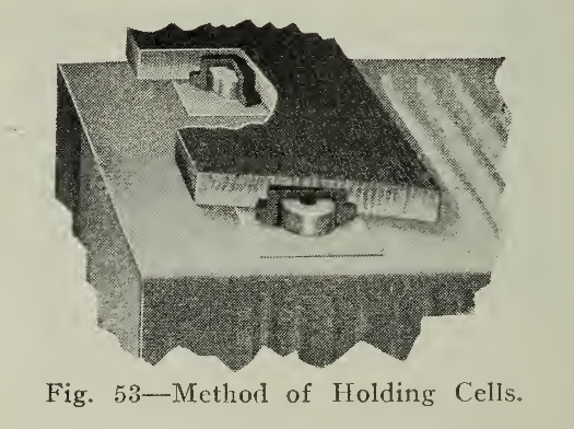
Cells, of size and number dictated by service requirements, are assembled in hard wood trays. (Fig. 48). The cells are provided with steel bosses projecting from the sides which rest in recessed hard rubber buttons embedded in the tray slats (Fig. 53). The trays permit of easy handling, ready inspection for damage, or quick exchange of cell as well as good ventilation and because of the rubber button suspension provide perfect insulation between cells.
The terminal posts or positive and negative poles referred to above are tapered and threaded at the top. The connectors (Fig. 49) are formed by swedging a nickel plated copper rod into two lugs bored so as to fit firmly on the tapered poles. The placing of the connector thus accomplishes the connection of adjacent cells and admits of connection between trays, parts of the battery, controller, etc. Where connections must be flexible a stranded conductor (Fig. 50) instead of a copper rod is soldered into the lug. Nuts are screwed tightly into position (Fig. 51) making connection firm and permanent at the same time admitting of quick and easy disconnecting. A disconnecting jack shown (Fig. 52) is used to remove the connector from the poles.
EDISON BATTERY
Care and Operation. In addition to the general instructions given above which apply to all storage batteries, the following are applicable to the Edison battery alone.
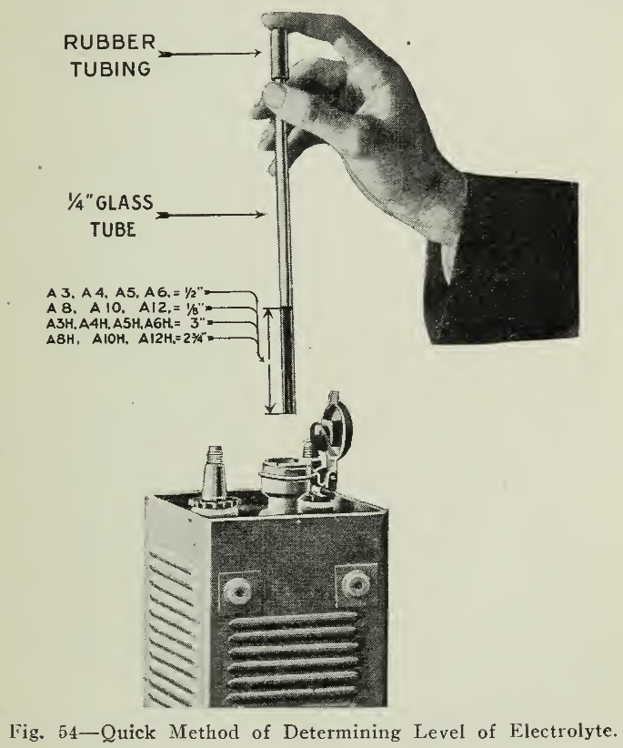
Upon arrival of the cells inspection should be made of the height of the solution level (Fig: 54) 1/2" above the tops of the plates for the A-3, A-4, A-5 and A-6 types and above for the A-8, A- 10 and A- 1 2 types, taking care to close the filler caps after the inspection. If the level is lower than these values spilling or damage in transit is indicated and the manufacturer should be notified.
In making connections connect the positive pole of the end cell of one tray to the negative pole of that in the next, etc. Where connections other than these are necessary the wiring diagram of the vehicle in question should be followed, although the terminals of the vehicle leads are generally lettered ore marked to correspond with the battery terminals for simplicity in assembling.
Charging. Before charging, the battery compartments should always be opened in order to allow ventilation. Inspection should be made of the height of the electrolyte and if not found to be correct then it should be brought to the proper level by the addition of distilled water only as described below and added before the charge is begun. (Page 135.)
The charging voltage required for various numbers of cells usually encountered in vehicle practice is in (Table 8) or may be easily calculated by multiplying the number of cells to be charged by 1.85 volts.
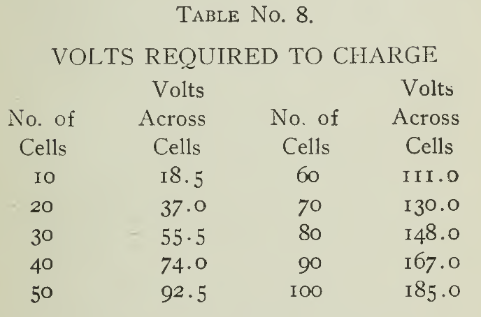
These voltages are the lowest sufficient to charge the numbers of cells given in series, at the normal rate toward the end of charge. While a few per cent, reduction in voltage will not materially affect the charge, allowance should be provided if it is required to charge at higher rates or charge several combinations of cells.
The initial charge should last for 12 hours at the normal rate for service. The "Normal Rate" is the catalogue rate of current for charge or discharge prescribed by the manufacturer.
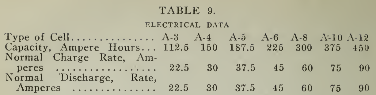
The normal charge for a battery practically discharged is seven hours at the normal rate (Table 9) line 3. The method of maintaining this rate as well as others described below is explained under "Charging Apparatus" Chapter VI. Should conditions prevent maintaining the normal rate, then the rate at the beginning may be set at a value approximately 50% above the normal at the start. This figure will vary somewhat depending upon the amount of resistance in the charging circuit. As the battery voltage rises, during the progress of the charge, this rate decreases and the average charging current will be approximately the normal rate prescribed.
When the battery is not fully discharged sufficient charging need only be furnished to compensate for the capacity removed. If the cells are half discharged then half of seven hours or three and one-half hour charge at the normal rate or its equivalent is necessary. In other words it is necessary to make the ampere-hour input about 20-25% greater than the ampere-hour output or if an Ampere-Hour Meter (Page 192) is used, set to operate 20% slow on charge.
The battery may be charged at any time, be the state of charge what it may, or may be discharged without other consideration than that of the capacity needed. Should a vehicle be capable of a mileage capacity of 6o miles, but 15 of which are needed per day, then a daily charge can be added sufficient to- compensate for the fraction removed or no charging done until the capacity is exhausted.
Where the daily mileage is apt to vary considerably the first method is probably preferable.
Overcharge. The first charge of the battery should be an overcharge, that is charging for twelve hours at the normal rate. This operation should be repeated after thirty and sixty days of service and after each renewal of solution. It should be understood that overcharging at the normal rate has no harmful effect at other times but is not necessary and therefore a waste of current.
Boosting. Hastening a charge, familiarly known as "Boosting" may in general be accomplished by using a high charging rate, the value of the current being governed by the temperature of the cells, a temperature of 115° being a practical limit. Experiment under many conditions has shown that the following are permissible :

In this way noon hour or other emergency charging can be done without injury to the; cell and in fact is recommended by the manufacturer as a very efficient method of operation when the necessary charging apparatus is available. This admits of a flexibility of operation, placing the electric vehicle in a class by itself. While the battery equipment required for usual demands may not be of capacity sufficient for great mileage, yet with proper boosting, continuous operation m.ay be obtained. A few minutes' thought will show that this is possible as there are very few vehicles which are not idle for the limited length of time necessary for the boost. It need not be accomplished without interruption, so any time can be called the right time. Simply a matter of giving the horse a drink. To secure the best results it is not advisable to charge at less than the normal rate as a lower discharge voltage will result reducing the speed of the vehicle for the following discharge. In cold weather the charging rate should be above rather than below the normal fate in order to heat the cells before use. Where vehicles are stored and charged in a cold garage it is often found convenient to arrange the charging so that the end of the charge will terminate with the current several times the normal rate. Where a battery is to be used in a locality of exceptionally low temperature and may be allowed to stand for hours at a time, as might obtain with a pleasure vehicle, then the battery compartment should be suitably protected from air circulation so that the heat may be retained and the output of the battery thus increased. If this means be made use of, however, the compartment should be returned to its original condition when moderate temperature conditions return, as the temperature of the cells would rise above that recommended for the most efficient results through a long life.
Discharge. Very little need be said in regard to the discharge except that for continuous operation, the rate of discharge should not exceed 25% above the normal discharge rate, which is identical with the normal charge rate for the same size cell. This, of course, does not affect sudden or short overload conditions at which there is no limit to the discharge current.
Solution. The cells as received from the manufacturer are filled with electrolyte of proper strength and (providing that no accident has occurred) to the correct level as explained above. As the battery is charged this level is reduced owing to evaporation of solution by gassing produced by the passage of current. As this evaporation is nearly entirely water, distilled water only should be used for replenishing; never potash and only distilled water. Water should not be spilled onto cells or trays and the filler caps should be closed except when filling or testing for height of solution.
The distilled water should be kept in carboys which have held no acid and which are distinctly labeled, so that by no possibility may acid be introduced.
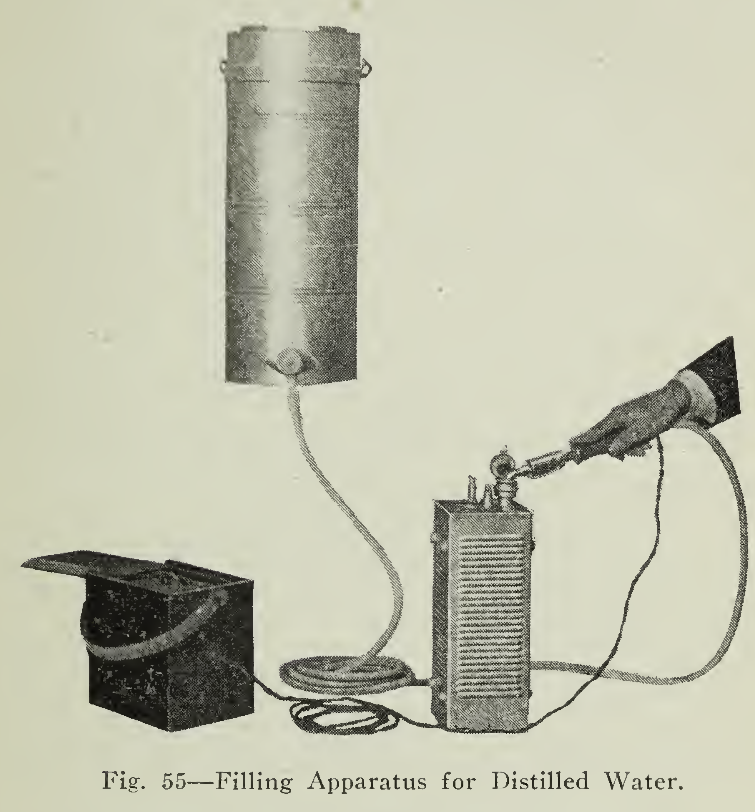
An electric filling outfit furnished by the manufacturer is arranged to save time and trouble in bringing the solution to the proper level with distilled water. It consists of a tank for the distilled water (Fig. 55) and a length of rubber hose attached to the filler which is designed to allow water to flow into the cell until the solution level has been brought to the proper height, when an electric bell circuit is closed by the solution and the bell rings. The spring valve of the filler is then released and the flow discontinued until the filler is placed in the next cell. This filler or tank should be used for no other purpose than the above.
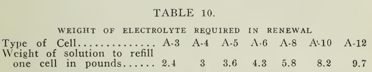
With use, the specific gravity of the solution will decrease in ordinary service, so that after a period of approximately eight to twelve months of continuous daily service or its equivalent, the solution should be tested with a hydrometer and if the readings of a majority of the cells are below 1.160, after full charge, the solution should be renewed. The weight necessary per cell is given in (Table 10) below.
Having the necessary amount of solution at hand, the battery should be thoroughly discharged, removed from the battery compartment and the solution removed by inverting the trays. Sloppage over the cans and trays should be avoided. By syphoning or with a glass funnel the renewal solution should be added immediately.
For export shipments, the potassium and lithium hydrate are supplied in dry crystalline form, ready to be mixed with distilled water, according to the instructions, at the destination.
At this point in the care it is well to emphasize that cleanliness is most necessary, for neglect is responsible for the majority of battery ailments. When the trays are out of the vehicle it is well to clean them thoroughly and also to see that no foreign material adheres to the cells. Usually a jet of dry steam or compressed air will accomplish this, the former being preferable. The compartment should be cleaned out well, made tight so as to keep waste and dirt out. Where cold weather is experienced it is important that this compartment be closed tightly, so that the heat generated during charge and discharge may be retained. If the temperature of the battery fall below 50° F. on discharge, the output will be materially lessened. The temperature of 50° F. here refers to the temperature of the electrolyte of the cell. If the compartment is properly enclosed the temperature outside the compartment may be very low, below zero in fact, without reducing the working cell temperature to the limit indicated. This capacity is accessible, however, upon raising the temperature of the cell to normal.
The highest immediate discharge capacities are obtained when the charging is carried on at a moderately low temperature, between 75° and 85° F. (not below 50° F.) and the discharge at a high temperature, not exceeding 115° F. As heat during the charge is more detrimental to the life of the plates than heat during discharge, it is recommended that the charging instructions (page 130) given above be followed as they are the result of a study of the many conditions involved in actual service.
With the above explanation, however, such variations may be made as the emergency demands or the requirements of the service dictate.
After replacing the trays in the compartment, care should be exercised in assembling correctly so that the end cells are properly connected as explained above. The contact surfaces of the connectors and tapered poles should be cleaned with fine emery cloth so that good electrical contact is obtained as poor contact would cause heating of the connection. After the cells have been on charge for a few hours, if the hand is run over these connectors, any poor connections will be found to be warm or even hot. If such is the case, the connectors should be removed, cleaned and again firmly secured.
POINTS TO BE REMEMBERED IN THE CARE OF THE EDISON BATTERY.
- Never put acid into an Edison battery or use utensils that have been used for acid; you may ruin the battery.
- Never bring a naked flame near the battery.
- Never lay tools or pieces of metal on the battery.
- Keep the filler caps closed at all times except when necessary for filling.
- Keep the cells filled to the proper level by adding distilled water only.
- Keep the cells externally as clean and dry as practicable.