Last Update: November 30, 2015
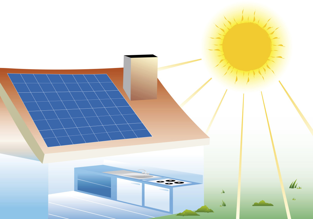
As we discussed elsewhere, the average home has enough roofspace for a solar array large enough to power both the car and the home. As we'll see here, there's a lot of variables at play such as the amount of southern exposure your house has, and the cost of the system you're willing to buy. The good news is that solar power costs are falling rapidly, making it a more and more economically feasible choice.
For our target system size, we'll borrow figures from the U.S. Energy Information Administration, saying the average “residential utility customer” in the U.S. consumes 10,837 kWh a year or 903 kiloWatthours (kWh) per month. That’s 30 kiloWatt-hours of electricity per day. This number seems high to me, but the EIA is the voice of authority in this matter. It is an average figure, so of course some households consume more and others consume less.
What we'll do here is follow the same process a Solar Designer uses to design a home solar power system. The steps we'll discuss below are:
- Site Survey: Determine the optimum location for the solar array and other system components
- Load Estimation: Determine how much power (kiloWatt-hours per day, etc) you need
- Energy Efficiency: What can you do to minimize power consumption, to limit the cost of the solar power system you buy
- Array Sizing: From the load estimate, geographic location, and site survey data, determine how big of a solar array is required. This tells you the number of solar modules, and how they're organized in the array.
- Energy Storage Sizing: This is optional, and determines how big of a battery pack is required to support the site. A consideration is the number of days of "autonomy" (running with no sunlight) supported by the system.
- Charge Controller: If there's an energy storage system, the charge controller must be selected.
- Inverter sizing: From the load estimate, determine how big of an inverter (synthesizes AC electricity) is required.
- Wiring, circuit breakers, etc sizing: Determine the other components to tie the system together, paying attention to electrical code rules.
- Racking systems: How is the system physically installed at the site.
- Grid interconnect: If the system is to connect with the utility grid, there are standards and requirements which must be followed.
At the very bottom is a resource guide with books and more that have even more details about solar power system design.
Site Survey
One of the first steps is to evaluate the proposed locations for the solar array and the components. Two key things we're looking for is:
- Site suitability - how much sunlight does it get during the day
- Initial determination of where the components will go
The ideal site for solar power is one where
- We can easily situate the solar panels to point directly south (not magnetic south)
- There are no obstructions to shade the solar panels
- Short wiring runs between solar panels and the connection to house wiring and the service panel
What you'll need to do is collect some information that will be used in later steps. You will be taking pictures, and starting a document. A word processor is useful, and so too is knowing how to transfer pictures into your computer for long-term storage.
 EV Charging Extension Cable for Electric Vehicle Charging Stations Compatible with All J1772 Plug")
Optimum Solar Array orientation
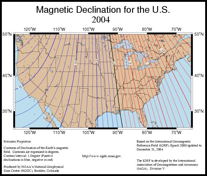
Determining True South: You may have heard there's a difference between True North and Magnetic North. The difference can be significant for solar arrays, since the panels need to be situated for the best solar exposure. The optimum is facing true south, at the correct angle to the ground surface, so the panels face directly into the sun.
The lines on this map shows how many degrees East or West to adjust a magnetic north/south reading to determine true north/south. For example, it shows that in St. Louis, and other cities along the 0 degree declination line, true north/south and magnetic north/south are exactly the same.
The simplest way to determine true south is by using a good quality map. True South is "straight down" on the map. Using an online service like Google Earth will let you zoom in on an overhead view of the building, and determine the true south in a way which shows you exactly which roof surface has the most southern exposure.
A magnetic compass is of course going to show magnetic north/south, and not true north/south. A declination map like the one shown above is good enough for our purposes.
There are also iPhone/iPad app's to show true north/south. They work by using GPS to determine your location, then calculating an offset from magnetic north/south. See:
Compass, Pro Compass,
GeolCompass, Commander Compass, for some examples.
Determining optimum tilt angle: The optimum insolation (absorption of solar power) occurs when the Sun is perpendicular to the solar panels. Knowing true south told us one aspect of this, and knowing the angle of the Sun is the other. The tilt angle is largely determined by your latitude. Someone at the equator is at 0 degrees lattitude, and therefore their tilt angle is 0 degrees, meaning the panels can be put flat on the ground for an optimum angle.
Of course both of these optimums vary throughout the day, and throughout the year, because the Sun's position changes all day long, and also as the Earth goes through the seasons.
Of course the absolute optimum is to mount the solar array on an automated tracking gimbal which points the array at the Sun as it moves through the sky. Doing so adds to the cost of the solar power system.
Determining the peak sun hours: This is a measure of the number of hours per day where available solar insolation equals 1,000 Watts per square meter. The 1000 Watts figure is a rule of thumb of the theoretical maximum solar energy possible. When solar panels are rated at 15% efficient, it means they produce approximately 15% of the theoretical maximum in certain standardized test conditions (STC). In conditions other than standard test conditions, solar panels perform differently.
For example, the higher the latitude of the site, or during Winter, the lower the Sun is in the sky. Therefore there will be fewer peak sun hours, and less energy captured at the site.
Determine the Peak Sun Hours figure through a yahoogle search ("Peak Sun Hours my location"), since there are plenty of websites publishing charts of this data.
Determining the Design Month: This will be the month of the year with the biggest need for electricity. You should optimize the solar power system design for the Design Month, to ensure the system provides enough power to last through that month. For example, the tilt angle at which to mount the array should be the optimum for the design month.
If the load is stable throughout the year, that is each month you consume the same quantity of electricity, then the Design Month is the month with the lowest solar insolation. Meaning, the month with the fewest peak sun hours, because the Sun is lowest in the sky. That will almost certainly mean your Winter Solstice month.
On the other hand, if your electricity consumption varies over the year, the Design Month should be the month with the highest consumption.
Determine shading: Real solar engineers have specialized tools to accurately measure the angle of objects (tree's, buildings, etc) that would block sunlight. For our purposes it's good enough to, once you've determined true south, observe at the site the location and height of these obstructions. Observe the pattern of shadows throughout the day, and if you can throughout the year. That will tell you which areas are shaded, and which are not.
Solar panels don't work in the shade.
Take pictures or make drawings showing where shading occurs, and keep these pictures in the file you're making.
Map the utility grid connection and other info to locate system components: What we need to know is the most likely place to put the system components like the Inverter. This should be located next to the service panel, because it will be feeding electricity into the household power system through the service panel. Take pictures of the building, the property, the service panel, and the wiring from the utility grid to the building.
Load Estimation - how much power do you need?
Face it, most of us blissfully ignore how much electricity we consume. We just pay whatever the electricity company says every month, and probably can't tell a kiloWatt-hour from a kumquat. We've written about kiloWatt-hours and other electricity measurements, as they pertain to electric cars, elsewhere on this site. The basic thing you need to know is that the kiloWatt-hour is the basic unit of electricity consumption. Your electricity bill will tell you the kiloWatt-hours you consumed that month, and may tell you the kiloWatt-hour consumption for the year.
What's a kiloWatt-hour? A kiloWatt-hour is 1000 Watts consumed over an hour. A Watt-hour is one Watt of electricity consumed over a one hour time period. Therefore, take ten 100 Watt light bulbs, run them for an hour, and you've consumed one kiloWatt-hour. That refrigerator in the kitchen, how many kiloWatt-hours does it consume to run 24 hours a day? Or per month?
Our goal in this section is to estimate your electricity needs, so we can eventually estimate how big of a solar array you need.
One estimation is to look at your historical electricity consumption. If you've saved your electricity bills, then leaf through those. Possibly the information is printed on the electricity bill. Some utility companies let you log into a website and browse historical electricity consumption data.
Your average daily electricity consumption is your yearly kiloWatt-hours consumed divided by 365.
With historical per-month electricity consumption you can answer the question raised earlier when determining the Design Month: In which month do you use the most electricity?
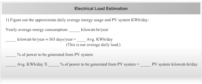
This explains the calculation more precisely. The "percentage of power" figure is the goal you have for how much electricity consumption you want to offset. With a grid connected solar power system, you have the luxury of not having to supply every last Watt of power for your building. Instead you can size the system to offset a portion of your consumption, perhaps saving some money on system costs.

This worksheet is a detailed inventory of your electrical gizmos and their power consumption.
Each row is one gizmo, such as light bulbs, computers, televisions or refrigerators. Going across the row you record data about the electricity consumption, and the number of hours per week it is used. The formula is:
Watt-hours = Watts x hours/day x days/week / 7
A 100 watt light bulb used 4 hours per day 5 days per week consumes on average 285 Watt-hours per day.
For AC Total Connected Watts simply add up the Watts AC column. This tells you the largest power consumption possible if every gizmo is turned on. For AC Average Daily Load simply add up the Watt Hours AC column.
Earlier we said we'd be designing for the 30 kiloWatt-hours per day national average. We'll just take as a given that whatever house we're looking at has appliances and other gizmos which add up to 30 kiloWatt-hours per day of electricity consumption.
Determining the consumption for each gizmo: Where do you get the numbers for this table? Guess? Actually, you don't have to because each gizmo will have a "nameplate" showing (among other things) the volts and amps it's rated to consume. Just copy those numbers into your spreadsheet and you're good to go.
Except, where do the hours/day and days/week figures come from? These will require some careful introspection as to what you actually do with each gizmo. Do you really know how much television you watch per day?
Then there's the gizmos that just run, and you don't know how often they're actually consuming electricity. The fridge is "on" and "running" all day long, but does that mean it consumes electricity 24 hours a day? No. Many gizmo's have a "duty cycle" meaning they run for awhile then stop. For example, the fridge only "runs" when it needs to lower the temperature.
Another way is to buy another gizmo to measure the electricity consumption of your gizmos. Just what we need, more gizmos right? In the case of kiloWatt electricity monitors, these gizmos will help you understand the real energy consumption in your home. What they do is measure and display electricity consumption data. Some plug into a wall socket, and you plug a gizmo into the meter, while others clip to the power lines. What they all do is give you a window into understanding electricity consumption.
These will also help you identify "phantom loads". Many devices still consume power when "off". Simply plug the device into an energy monitor, then turn it off, and see what happens to the electricity consumption. The best way to avoid phantom power consumption is to plug the device into a power strip, and then use the switch on the strip to turn the device off. Think carefully about each device - for example, the clock on the VCR is powered by phantom power - because you'll want some devices to actually consume phantom power.
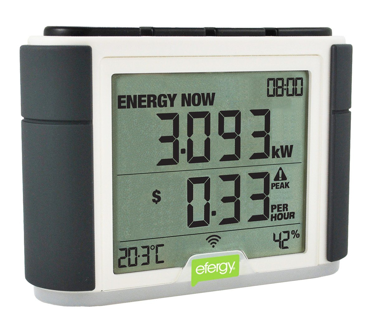
 Efergy Elite Wireless Electricity Monitor
This is useful for measuring the energy of an entire house, or of a given device. You clip sensor units to wires - the sensors are meant to be installed inside your service panel - that wirelessly transmit data to a display unit. The display can be put anyplace that is convenient.
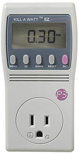
P3 International P4460 Kill A Watt EZ Electricity Usage Monitor
This plugs into a power outlet, and you plug your gizmo into the outlet on the front. It measures power flowing through the meter, showing the numbers on the screen.
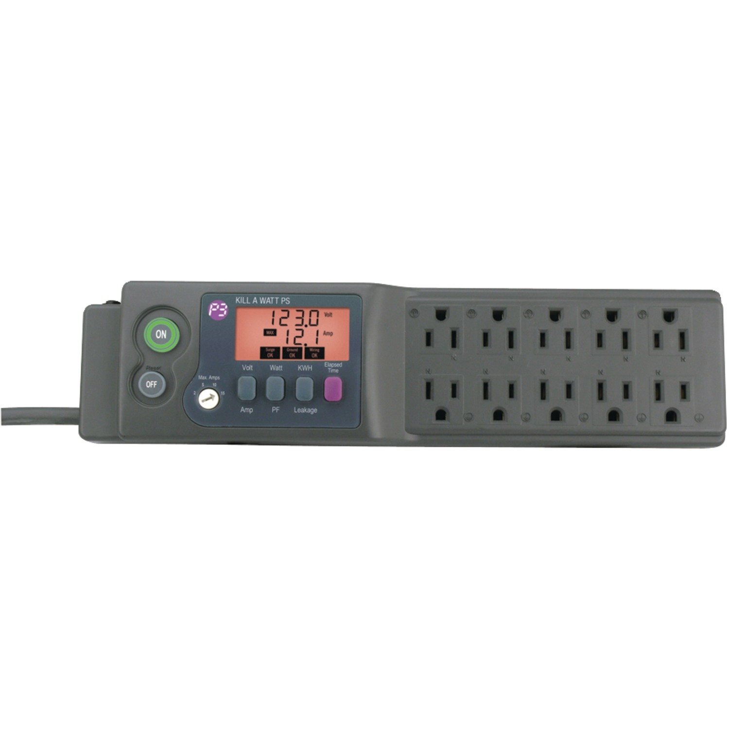
P3 INTERNATIONAL P4330 KILL A WATT PS-10
This is the same concept as the previous product, but embedded in a power strip. With the P4460 it can sometimes be tricky to use that meter, on a power outlet, while sharing that outlet with other devices, depending on how the specific outlet is installed. This power strip of course can connect to any outlet, and then it can easily monitor the power consumption of several devices at once.
Surge Loads: Some devices consume a surge of power at startup. A great example is the electric motor on a pump where power consumption surges when its starting.
Surge loads affect the "AC Total Connected Watts" calculation. The rule of thumb is that a surge load is 3 times the rated load.
Energy Efficiency - decreasing the power requirements
Before paying money to buy a solar power system it's wise to reduce your electricity consumption. Switching to LED light bulbs, or an energy efficient refrigerator, will save a lot of electricity. Having calculated the required array size above, you can see that consuming less electricity means you'll need a smaller solar array. That will then result in lower system cost in every component.
Often the recommendation to cut electricity usage is to switch to propane or natural gas powered appliances. A propane refrigerator consumes no electricity and therefore reduces the solar array requirements.
While this is true, there is another side of this to consider: Propane and Natural Gas are fossil fuels. If your over-arching goal is to eliminate fossil fuel consumption, then you do not want to use propane or natural gas powered appliances.
Here's a few ideas for optimizing refrigerator electricity requirements (that do not involve fossil fuels):
- DC powered fridge's are available, and can work if your solar power system includes a battery backup system. DC powered appliances are more efficient by avoiding the conversion loss in the Inverter.
- Look for a well insulated fridge - with a high R value.
- Locate the fridge where it won't be struck by sunlight, is not next to the oven, and is not sitting against an outside wall.
- Carefully study the Energy Star ratings and other energy consumption information you can find.
Efficient clothes washers and dryers are also available. Traditional clothes dryers damage clothing - that lint in the lint trap is the evidence of the damage. The two choices given here don't damage clothing, use a fraction of the energy, and get the job done in an excellent fashion.

The Laundry Alternative Nina Soft Spin Dryer, Ventless Portable Electric Dryer
This dryer does its job solely by spinning clothes, without creating heat. You put the clothes in the compartment, close the lid, and they're spun at a very high rate. Water literally pours out of the clothes. The whole goal of "drying" clothes is to remove the water, and this is an extremely efficient way to do so.
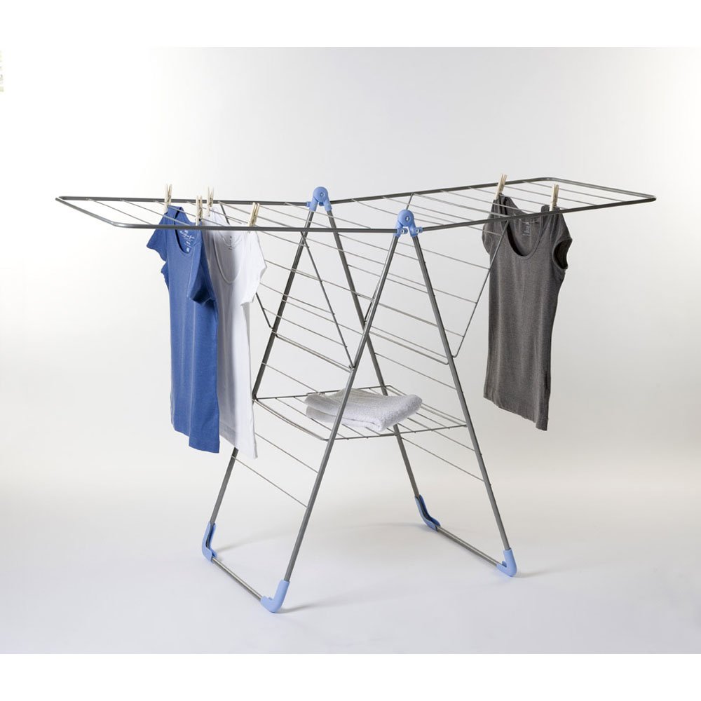
Moerman 88346 Y-Airer Indoor Folding Clothes Drying Rack
There are all kinds of clothes drying racks, or clothes lines, on the market. You can simply air dry clothes without putting them through any kind of drying machine. This particular rack is very well made, constructed of sturdy metal, and it quickly and easily folds so you can stash it away when not in use. It easily adjusts to several arrangements as well.
Understanding Solar Panels
Now that we've estimated the electricity consumption, we can estimate the photovoltaic panel array size required to supply enough power. But before we get to calculate the array size, we have to go over some basic information about solar modules.
Solar module/panel characteristics
The basic characteristic of photovoltaic (solar) panels is that when struck by sunlight, the energy is converted into electricity. A solar "module" is made of several (or dozens) of solar cells, which are wired together to produce the output circuit. A solar "array" is a group of modules wired together in a larger system. The word "panel" is sometimes used to refer to a single solar module, and sometimes to refer to a string of modules that are then part of a larger array.
The solar cells are themselves a semiconductor using technology similar to the chips in electrical gizmos. Semiconductors are made of silicon that's "doped" with materials creating the desired circuit. Normally silicon is an insulator meaning electricity would not flow. The doping materials are what makes it a semiconductor, and are what gives solar cells the ability to convert sunlight to electricity.
Solar module ratings
Solar module ratings are measured under what's called Standard Test Conditions. The STC is solar irradiance of 1,000 Watts per square meter, and at 25 degrees Centigrade. Many solar panels have lower perform in hotter weather. Therefore it's important to mount modules so that air flow can keep the panels cooler, and if the system is destined for a hot climate then to select modules that work well when it's hot.
The module ratings are these attributes, which will be shown on the specification label:
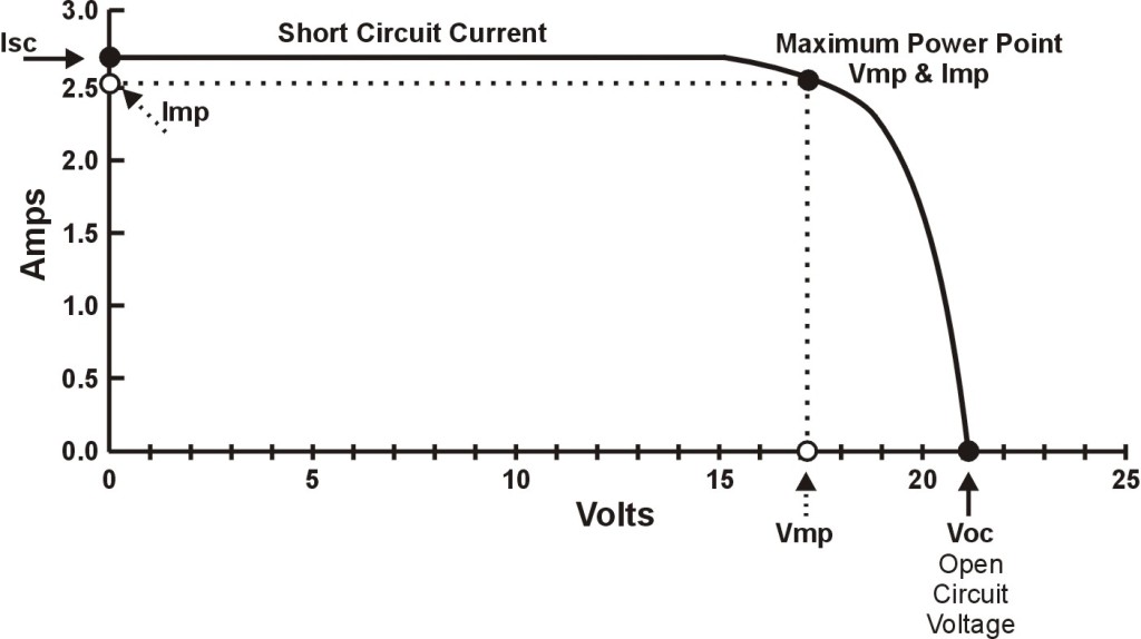
- Vmp, Imp: Voltage (V) and current (I) at the operating point where the maximum output will be produced.
- Voc: The "open circuit voltage" is the maximum potential voltage when no current is being drawn from the module.
- Isc: The "short circuit current" is the maximum amperage when you the module's output wires are directly connected together (shorted).
- Max Power: Multiply together Vmp and Imp to determine the maximum wattage.
Because those ratings are measured under standard test conditions (STC), the module will behave differently under other conditions. For example, if the solar irradiance (the strength of the sunlight) is weaker than 1,000 Watts per square meter, the panel will produce fewer amps and somewhat fewer volts.
Shading produces a similar result, as does mounting the panels at a non-optimum tilt angle. When we discussed determining the optimum module orientation earlier, it was to maximize the output from the modules.
Grid connected or standalone systems, either with or without battery backup
There are three types of systems to choose between:
- Grid connected: Solar panels solely feeding power to building, selling excess to grid, and no local energy storage
- Grid connected with battery backup: Adds local energy storage
- Standalone: No grid connection
The first is the least expensive because it's the simplest system. But you have no battery backup, hence when the grid goes down your power goes down just like everyone else. Additionally, as solar power is more widely adopted some areas are adopting rules requiring "Net Zero Energy Export" meaning to prevent electricity being sent from a home installation past the service panel. If those rules become widespread the only response is to add local energy storage to every solar power system.
The standalone systems are for off-grid applications - the stereotypical cabin miles from anywhere - the remote telecommunications micro-wave tower - the portable speed limit signs. The solar panels in an off-grid system are used to keep a battery pack charged up, and the battery pack is sized to supply several days of electricity.
Your choice between these three types of systems determines the components that are needed, the array size, the installation process, and more.
Series or parallel wiring solar modules
We're almost ready to calculate the necessary array size given the data gathered above. Before doing so we must go over the ways a solar module array can be wired to generate the desired voltage and amperage outputs.
One has to understand the mathematics of connecting solar panels. The mathematics are identical to when you connect batteries together, so if you're already familiar with this then it'll be a nice review.
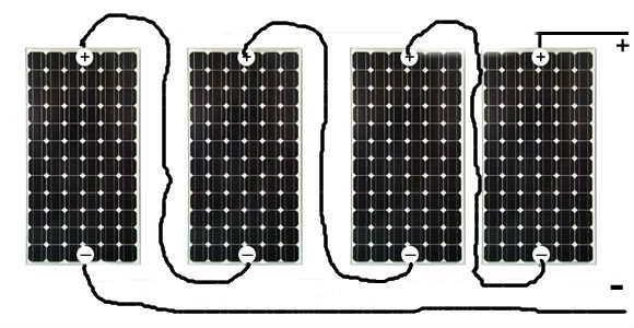
Panels connected this way are "connected in series" or "series connected". Mathematically, the voltages are added together while the amps capacity stays the same. That is, if each panel is producing 12 volts 5 amps, the total electricity production will be 48 volts 5 amps, or 240 Watts.
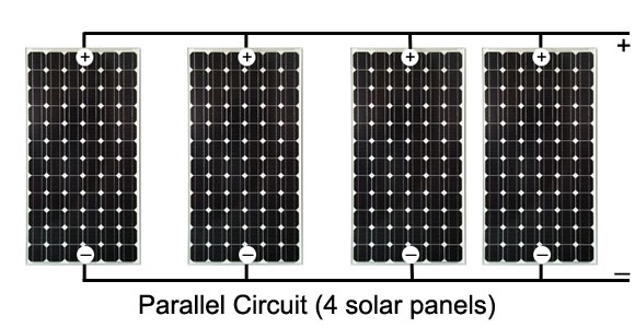
Panels connected this way are "connected in parallel" or "parallel connected". Mathematically it is the amperage which is added while the voltage stays the same. That is, with 12 volts 5 amps per panel, the total electricity production would be 12 volts 20 amps, or 240 Watts. Note that the power produced (Watts) stays the same in both cases.
There are several reasons we'll go over later to wire an array for a high voltage.
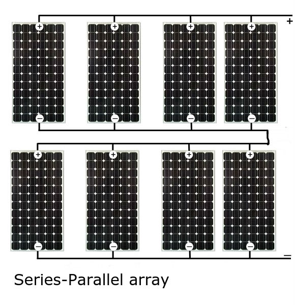
What do you think would happen with two parallel connected arrays connected in series? We've already discussed how connecting things in parallel adds the amperage, and connecting in series connection adds the voltage.
Going with our 12 volt 5 amp panels, we have two parallel connected sub-arrays each producing 12 volts 20 amps, and they're connected in series. Meaning the voltages of the sub-arrays add up, giving us 24 volts 20 amps, or 480 Watts.
A large-scale solar array that covers a whole parking lot will use this technique. The total system voltage is limited by the capabilities of the inverter, and is usually kept below 600 volts.
Micro-Inverter wiring: A new option for wiring solar arrays is to use micro-inverters. Instead of a single large inverter, a small (micro-sized) inverter is mounted to each panel. In this case the panels do not produce DC voltage, but produce AC voltage, at either 240 volts or 120 volts. In this case all micro-inverters are wired in parallel so the end voltage is 120/240 volts and the amperage is added together.
Designing the solar array size
We now have enough information to let us calculate the number of panels required. Earlier we declared that we'll design for the national average of 30 kiloWatt-hours per day.
There are actually two different calculations depending on whether the solar power system does or does not have a battery pack. If there's a battery pack, then we have to consider the array size required to keep it topped up. For a pure grid-connected system, we only have to consider an array large enough to offset the desired amount of on-site electricity consumption.
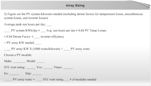
This worksheet is used for pure grid-connected scenarios, where there's no battery backup.
Since we're designing for 30 kiloWatt-hours per day, that could be the number we put in the first box. But, suppose it's desired to only cover 70% of the electricity consumption? This is one way to shave costs off the system, to offset only a portion of the electricity. In such a case you'd enter 21 kiloWatt-hours as "PV system kWh/day" (30 * .7 = 21).
For average sun hours, I suggested to yahoogle "peak sun hours your location" and look at the charts that come up. Over at
Solar Direct they have a useful chart with lots of U.S. cities. Let's take Spokane Washington as the city, and it has only 4.8 sun hours per day as a yearly average.
For "inverter efficiency" let's enter 0.9 (90%).
I just went through that calculation, and came up with 6.57 array kiloWatts needed to cover 21 kiloWatt-hours of electricity production (70% of 30 kWh). The PV Array Watts figure is precisely 6,576.
The last section of the worksheet tells us the number of modules required. In the middle we record the characteristics of the chosen module, and on the last line is a simple calculation to determine the number of modules.
For example, with 300 watt modules, we'd need 21.92 (round up to 22) modules to supply 6,576 watts.
To size an array with battery backup, we must first calculate the size of the battery backup. Which means we must head to the next section.
Energy Storage sizing (optional)
Adding a battery backup system, also known as energy storage system, is optional but should become more popular due to a pair of influences. First, lithium-ion battery costs are falling rapidly thanks to improving technology and economy of scale connected to electric car production. Second, government regulators are beginning to ponder requiring net zero energy export, meaning that solar power systems will be required to have local energy storage so that the timing of release of energy into the grid can be controlled.
It's undesirable for electrical grid stability to release energy into a grid that's already oversaturated with electricity. Hence grid operators want to control the timing of energy release into the grid. That fact means we'll possibly face a requirement that all solar power systems have local energy storage, along with smart grid control, to help the grid operators keep the whole system running smoothly.
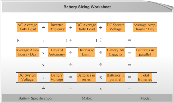
Remember that the mathematics for batteries and solar panels are identical. That means a series connected string of batteries add the voltages together, and a parallel connected string adds the amp-hours capacity together.
We're designing for 30 kiloWatt-hours per day, and are assuming the inverter is 90% efficient, and assuming there is zero DC daily load. There would be a DC load if you had DC appliances, like a DC refrigerator. Finally let's assume a 48 volt system.
Calculating the first row gives us 694.4444 amp-hours per day.
The "days of autonomy" figure asks us the expected length of power outages. If we expect a five day power outage, then we design for 5 days of autonomy.
The "discharge limit" relates to the requirement to keep the battery pack from discharging too deeply. Batteries are damaged when discharged too deeply, and because of their expense we want to design the system to lengthen the battery pack lifetime.
Where solar modules are rated in volts and amps, batteries are rated in volts and amp-hours. An amp-hour measures how many hours a battery can deliver a given amperage.
Assuming 4 days of autonomy, a discharge limit of 50%, and 350 amp-hour batteries, we calculate 16 batteries in parallel.
We'll assume the batteries are 12 volts (common voltage), so therefore a 48 volt system requires 4 batteries in series. That means we require 48 batteries in total for this system. That's a total of 16.8 kiloWatt-hours of energy storage, or about as much as is in a Chevy Volt.
Now we can move on to calculating the array size required for this system.
Earlier we calculated 694.4444 amp-hours per day. With a battery efficiency of 80% and 4.8 peak sun hours per day, the "Array Peak Amps" required is 180.989 (round that up to 181 amps).
For the rest of the calculations need to have selected a given module so we can plug its characteristics into the equations.
For a module supplying 5.02 amps, we need 36.055 (a.k.a. 37) modules in parallel. If that module supplies 12 volts, we need 4 modules in series. Therefore the whole solar array is 148 modules.
Charge controller sizing (optional)
If your system has a battery system, it must have a charge controller. The charge controller ensures that the battery pack is not overcharged as well as doing other useful functions.
It may not be possible to match the array voltage with the battery pack voltage. Batteries often come in multiples of 12 volts, where solar panels rarely do. Therefore, charge controllers often have the ability to change the DC voltage from an input voltage to a selected output voltage.
A highly desired feature is "MPPT" or "Maximum Power Point Tracking". These adjust the conditions so that the array is operating at the optimum voltage/current, and therefore outputting the optimum power level. MPPT controllers are more expensive than the older style PWM charge controllers.
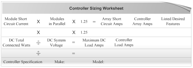
The first row of the worksheet calculates the maximum current which will be produced by the array. The charge controller must be able to accept that many amps.
Inverter sizing
The next step is to plan what inverter to buy, starting by determining how big of an inverter is required. Inverters are rated by the wattage they handle, and then there are several important features to consider.
An inverter synthesizes an AC current from a DC power source. They cannot make a perfect sine-wave AC signal, but modern inverters use advanced electronics for both high efficiency and a more accurate AC signal. Some produce a 120 volt, others a 208 volt output (to match the voltage of commercial buildings), others 240 volts, and some even produce 480 volts. Each of these voltages corresponds to different power system scenarios.
There are three classes of inverters to match with the three types of solar power systems:
- grid-tied
- grid-tied with battery backup
- standalone
Synchronous or line-tied inverters are used in concert with a connection to the power grid. They must safely interact with the conditions of the electrical grid, for example to synchronize the AC wave form with what's on the grid for compatibility when power is imported or exported.
Battery-less inverters often include MPPT support to optimize power production.
Modern inverters come with several desirable features - high efficiency - low standby losses - good frequency regulation - and power factor corrected. Useful optional features include
- Remote control and data monitoring
- Load transfer for systems with multiple inverters, in case one fails
- Capability of parallel operation, allowing the system to have multiple inverters
The key characteristics in selecting an inverter for a battery-less grid tied system are
- Watts output AC: The maximum power output of the system. It of course has to be larger than the "AC Total Connected Watts" value calculated earlier. For a large system you may need to use multiple inverters to have enough power output.
- Input voltage: Most grid-connected inverters can handle input voltages between 70-600 volts DC. The inverter of course must be able to handle the array voltage. In order to handle extra sunny days where the voltage is higher than expected, don't design the array voltage to the absolute maximum of the inverter. In fact, one must take care that the array voltage never fall outside the minimum and maximum input voltage range. Doing so can damage or destroy the inverter.
- Output voltage and frequency: This voltage must match the voltage (and frequency) of the local utility grid, since it must produce AC power that's compatible with the grid.
- Battery charging: It's helpful if the inverter can handle battery charging, to top up the back-up battery from grid electricity.
- Automatic shutoff if battery level is too low: It's very bad if the battery pack voltage goes too low, because of damage to the pack.
- High current capability to handle surge loads: Some sites have gizmos with a high surge demand, like when starting up a motor, and the inverter needs to supply that surge.
- Generator auto-start-stop: In case there is an on-site generator, it's useful if the inverter can automatically start it when needed. The purpose of having battery back-up is the ability to operate even if the grid goes down, and having an on-site back-up generator extends that ability to keep on running through a long-term power outage.
The key characteristics are the same as the battery-less inverters, with this addition:
- DC input voltage from batteries: Where a battery-less inverter has DC input voltage corresponding to the solar array, a battery back-up inverter has its DC voltage tied to the battery system. A common voltage for the batteries is 48 volts.
A standalone inverter has many of the same characteristics as a grid-tied battery back-up inverter, but it does not interface with the grid.
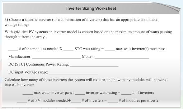
This first worksheet calculates, based on the peak power output of the array, and the capacity of the chosen inverter, how many inverters are required for the system.
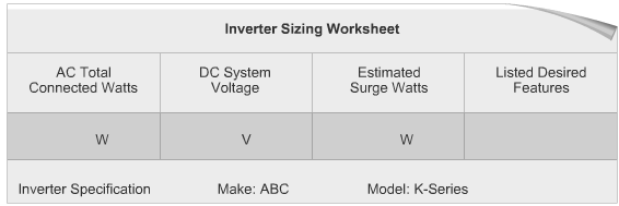
This second worksheet is more like documentation of the system characteristics as it relates to the inverter.
Solar Power System Components Diagram - Grid Connected
Before we calculate the wire sizes required, we need to understand how the components are connected together to make a complete solar power system.

A "DC Combiner Box" is needed for some systems where there might be multiple strings. It's basically an electrical junction box where you can connect things together.
The "Safety Disconnects" we'll discuss later, but are required to shut down the system in case something goes awry, or when you're performing maintenance.
The "Service Panel" is simply the normal existing electrical service panel that's the regular interface between the electrical grid and the building. The output of the inverter must be connected to the service panel through a dedicated circuit breaker. That means before the system can be installed, there must be space in the service panel for a new circuit breaker.
Solar Power System Components Diagram - With Battery Backup
Adding a battery back-up to the solar power system adds a few more boxes to the system, and otherwise it's the same.
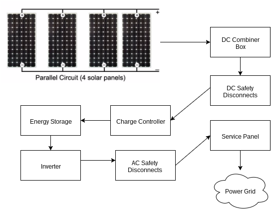
The new parts are the "Charge Controller," which handles keeping the energy storage system charged, and the "Energy Storage" (battery pack) itself.
These diagrams do not show the required grounding lines. Some of the lines in these diagrams should have been bi-directional, because electricity does flow from the grid into the system on occasion.
Wiring sizing
The wiring has to be able to safely carry the current required to run the system. Any wire acts like a resistor, and copper is commonly used because it has the least resistance of any metal (other than gold or silver). To minimize resistance one must use wire that's thick enough for the power flow, and otherwise the wire will heat up and possibly catch fire.
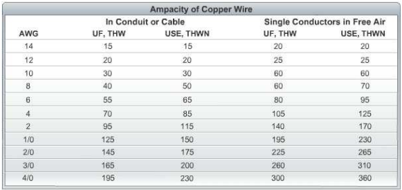
This first chart shows us the thickness of wire required for any particular current rating. The smaller the "AWG" number, the thicker the wire. The sizes marked "1/0" to "4/0" are even thicker, and are commonly used in welding systems.
Notice the chart is delineated in amps and not volts or Watts. It doesn't matter what the voltage is, a 14 gauge wire is only safe for 15 amps. The rating in this chart is not for continuous loads, but for instantaneous currents. The National Electric Code (NEC) requires that for a continuous load -- which a solar power system is -- be run at 80% the rated amperage. That means the 14 gauge wire rated for 15 amps can safely run a continuous load of 12 amps.
Therefore a 14 gauge wire can carry 2400 Watts at 12 amps 200 volts, or 144 Watts at 12 amps 12 volts. A high voltage system is one way to save money. The high voltage lets you carry higher Wattage through a skinny wire.
 Wire sizing calculators
These iPhone/iPad calculator applications can be easier and more powerful than hunting through the charts and formulas shown here.
This means at every step of the system diagrams shown above, the components and wiring must be rated to handle at least 125% the current flowing through that stage of the system. (125% is another way of expressing the 80% rule)
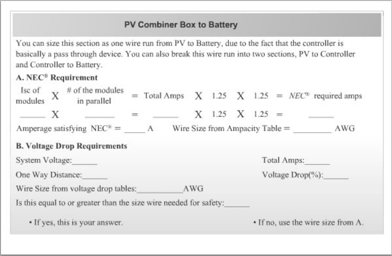
For the wiring between the solar array and inverter (for pure grid connected systems) or between the array and battery pack (for battery backed systems), the rating must be multiplied by 125% a second time as shown in this worksheet. That's because the NEC code recognizes that on really sunny days there may be excess power production.
Another thing to take from this worksheet is the voltage drop on long wire runs. When designing your system it's best to keep wire runs short in order to avoid resistance. The resistance causes a voltage drop (and possibly heat) which reduces the system efficiency. To avoid the voltage drop you must lower the resistance of the wire, by using a thicker wire gauge.
Voltage Drop Calculators
Charts to determine voltage drop are available but it is a complex enough subject that a calculator application is a better deal. These voltage drop applications make it easy to make the calculations. Some of the apps listed above also handle voltage drop calculation.Overcurrent Protection and Disconnect sizing
To protect the system from various failures, the National Electric Code requires various protection devices.
- Fuses and/or Circuit Breakers: To automatically disconnect the circuit in case the current flow is too high.
- Disconnects: To disconnect the system while you're working on it, or installing it.
Of course both of these must be sized appropriately to the current flow. The process is similar to what we went through in designing the correct wire size.
It's of course more convenient to use circuit breakers than fuses. If the current gets too high but recovers later, a blown fuse is trickier to replace than it is to just flip the circuit breaker. On the DC side of the system you must use a DC fuse, and an AC fuse on the AC side of the system.
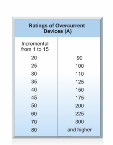
This chart tells you the required increments for overcurrent device ratings. You must know the "NEC Required Ampacity" of each given segment in your circuit, then consult this chart to find the next higher rating. So if your circuit has an Ampacity of 32 amps, you'd use a overcurrent 35 amp device.
Remember that the Ampacity is either the current times 1.25, or current times 1.25 times 1.25, depending on the segment requirements. In general it doesn't hurt to use a device larger than required, other than paying a slightly higher cost.
The NEC code (NEC 2005, Article 690.9(A)) requires that an overcurrent device be installed in each ungrounded conductor segment. Basically this means a circuit breaker is required between the array and charge controller, between charge controller and battery pack, between battery pack and inverter, etc.
The disconnect devices can simply be the circuit breakers (NEC 2005, Article 690.15). It can also be a switch, of the appropriate rating as indicated by the table above. Because the disconnect cannot leave "live parts", it cannot be a simple cable connection.
Grounding
It's very useful for the solar power system to be well grounded for protection, if only because it'll be located outdoors and may be hit by lightning.
The grounding wire has to be connected into the actual ground, and does not normally carry current. It's meant to carry current if something awry happens. For example a failure could connect the power circuit to the equipment box, and if someone touches the box they could be electrocuted. Grounding the equipment boxes prevents such an electrocution.
The Grid Interconnect
Earlier we said the inverter is connected to the service panel, and is therefore tied to the electrical grid. In order to be allowed to do so, you must first get an "Interconnection Agreement" with the local utility. This specifies the terms and conditions of connecting a PV system to the utility grid, as well as technical requirements to ensure safety.
That means we must interface with bureaucracy. Deal with it. Fortunately because solar power systems are becoming more popular, the process should be getting easier.
"Net Metering" is where any electricity "sold" back to the utility grid is subtracted from your electricity consumption. At the end of the month you're billed for any electricity you consumed above the amount sent into the grid.
Standard electrical meters simply spin backward when electricity flows out of the service panel to the grid. That's the net metering process in a nutshell, when the meter spins backward.
Racking
Racking systems are used to fit solar modules together to build a solar array. Solar modules themselves are generally a metal frame, containing solar cells sandwiched between glass. Racking systems fit to the metal frames of the modules, to make a larger frame system. The rack of modules is then built onto other structures such as:
- Building-integrated systems are used as architectural elements in a building
- Roof mounted arrays are bolted onto existing roofs
- Ground mount systems are instead built onto structures planted on the ground somewhere. An example is when a solar array is built over a parking lot.
- Pole mounted systems are built onto the top of a pole, and often have a solar tracking system so the array can pivot to follow the Sun's motion
The racks provide extra stability and rigidity, and must be designed to hold together even in high winds. They can also be designed to hold the panels at an optimum angle to capture more sunlight.
Some tracking systems pivot on multiple axes while others simply pivot on one axis. The latter systems would start the day with panels facing east, and slowly rotate them to face west at the end of the day.
Installation
Now that we've gone over all the components of a solar power system, let's talk a little about installation.
The site evaluation performed at the beginning will have identified a location for the array. That location needs to be as free of shading obstacles as possible, and have good southerly exposure. The evaluation will have also identified the location of other components, and the routing of power cables between the array and the rest of the system.
The first step is to install the array and racking system in the designated location. You then wire the panels together in the desired arrangement. This will give you one or more pairs of positive and negative contacts where the array will output its power.
Since it's likely you'll be spending some time on a roof at this point, there are a lot of safety procedures to follow. The installers need to wear harnesses to prevent falling off the roof, and to carefully work with tools and components.
At this point you must measure the voltage and other characteristics to ensure the array was correctly wired together.
The next step is to set up the battery system and charge controller, if necessary. The batteries must be kept in an enclosure to protect them from the elements.
Run power cables from the solar array to the controller, from the controller to the battery pack, and also install the overcurrent and disconnect devices.
The next step is to install the inverter. The input side of the inverter is wired either to the battery system, or to the array, depending on the system design. The output side of the inverter is wired to the service panel. And of course overcurrent and disconnect devices are installed where needed.
Before turning anything on, you must check the wiring and that voltages are as expected. It's required to go through each component and verify that what was installed has the correct rating. These systems are running at high voltages and power levels, and if installed incorrectly can result in death or fires. This isn't something to fool around with, be careful.
Before the grid connection can be enabled, electrical inspectors from the city/county and/or utility company must inspect the system.
Further Resources
Photovoltaics: Design and Installation Manual
This is the training manual for professional solar designers. It goes over the solar design process in great depth, and has all the worksheets (and more) shown above. In the back is many pages of solar power data for cities across the U.S., and an extensive glossary, and more. The explanations are clear and straight-forward. The book is meant to be used in classrooms, and therefore starts with the basics of solar power. Each chapter adds knowledge of a specific section of solar power system design, and it all works together.
Solar Electricity Handbook - 2017 Edition: A simple, practical guide to solar energy - designing and installing solar PV systems
The author, Michael Boxwell, is both an electric vehicle expert and solar designer with years of experience in both fields. Now in its ninth edition, the book assumes no previous knowledge of solar electric systems. The book explains how solar panels work and how they can be used. It explains the advantages of solar energy and the drawbacks that you need to take into account when designing a solar power system. The book is suitable for enthusiastic novices for building professionals and architects learning about photovoltaics.
Build Your Own Low-Budget Solar Power System
This book is meant to help people set up a simple, small-scale, low budget solar power system. The author has lived off-the-grid for over 10 years. He says the most common question is how to set up a small solar energy system to power a cabin or camper, or to keep a refrigerator and a few lights on if the grid goes down.
DIY Solar Projects
This book explains not only photovoltaic solar power systems, but solar cookers, hot−water heaters, and hot−air collectors. It demonstrates how these can be built and mounted using ordinary materials.
Convert Your Home to Solar Energy
This source book covers all the relevant technologies, including solar space and water heating as well as photovoltaic electricity. The author launched a solar design company in New England that he ran for over 30 years. That gave him the opportunity to design thousands of solar systems.
Rooftop Revolution: How Solar Power Can Save Our Economy-and Our Planet-from Dirty Energy
This book explains how the "ascent of solar energy is upon us". Solar energy production has soared in recent years as has employment in the field. This book doesn't help you with solar power system design, but to understand the policy issues and market forces. It refutes lies spread by solar power opponents, and shows that we need a rooftop revolution to break the entrenched power of the coal, oil, nuclear, and gas industries. The author is the founder of SunGevity, a large company providing rooftop solar design services across America.
Solar PV Off-Grid Power: How to Build Solar PV Energy Systems for Stand Alone LED Lighting, Cameras, Electronics, and Remote Communication Power Systems
This Book is written to be a resource in building your own Solar PV supply for remote Cameras, LED lighting systems, Communication, Sensors, and remote Cabin, and Home Power systems, with Solar PV Power system examples. Solar PV panels, sized properly, produce reliable, and predictable energy production, despite daily variations, when calculated properly for each month. Tap into PV Panels to charge battery banks for reliable DC, and, with inverters, AC power on demand. Remote site power supplies, designed, and installed properly, offer real power for running a variety of electronic, motor, and large draw devices.